“Gaia” or the Living Planet in a Living Universe.
Natural Resource Management Versus Bioenvironmental Management:
The human decision to use a material enables it to be labeled a resource.1 The total flow of a material from its state in nature through its period of contact with man to its disposal can be termed a resource process.2 Efforts made to achieve orderly and sustainable use of Natural Resources can be termed as the Management of Natural Resources. The attempt to minimize the impact on the environment of Natural Resource exploitation is termed as Bioenvironmental Management. The goal of Natural Resource Management is oriented more towards development and change rather than the preservation of nature. As a matter of simple economic sense, resources are managed in order to keep them available. It was the growing awareness of the inter-dependence between the living and nonliving components of the natural world that has led to the more dynamic concept of BioEnvironmental Management.3 “It is recognized that it is the Bioenvironmental systems of the planet which provides resources and that any resource process must be rationally managed in order to ensure a sustained yield – preferably one which is capable of due increase, but in which the existence of limits is recognized.”4 Thus, it can be safely said that Natural Resource Management is the process of ensuring the sustainability of resource exploitation. On the other hand, Bioenvironmental Management is the process of ensuring the sustainability of the life-supporting environment.
There are two main avowed aims of Bioenvironmental Management. The first being the reduction of the degree of stress, upon an ecosystem, from contamination or overuse. The second is the pursuit of short-term strategies that preserve long-term options while retaining a degree of flexibility. Irreversible environmental change is anathema to Bioenvironmental Management and is exactly what it seeks to avoid at all costs. However, economic exploitation is not derided as it is recognized that natural resources need to be used in order to ensure the survival of the human race. However, it is this very long-term survival that has prompted Bioenvironmental Management.
Conservation broadly means using without using up. Pollution control is playing an expanding role in the Conservation Movement. However, it is seldom realized that pollution is the end product of a destabilizing process of the biosphere on a global scale. The proponents of “Spaceship Earth Economy” as an alternate to the present “Cowboy Economy” are still far away from the concept of “Gaia” or the Living Planet in a Living Universe. While concepts may differ it is no longer avoidable to realize the fact that rank and short-term exploitation has to be stopped immediately.
The contrast between the population-resource relationships of different types of countries allows the construction of regional classification.5 Pakistan lies in the type “D” category or most unfortunate group. Here there is no deficiency of appropriate technology. Rather it is not communicated to the “bewildered poor.” The population puts pressure upon resources and is growing at alarming rates. Are we already classified as an MSA (Most Seriously Affected), the subgroup within this group? China is an example of an escape from this category. Can we emulate the example of our great neighbor? With the requisite communication of the absolute necessity of employing Bioenvironmental Management and a clear “Way Ahead,” the answer is YES!
Rain Water Harvesting:
Definition:
Water Harvesting refers to the collection and storage of rainwater and also other activities aimed at harvesting surface and groundwater, prevention of losses through evaporation and seepage and all other hydrological studies and engineering interventions, aimed at conservation and efficient utilization of the limited water endowment of a physiographic unit such as a watershed.
1 I. G. Simmons 1974.
2 Firey 1960.
3 Bennett and Chorley 1978, Holling 1978.
4 I. G. Simmons The Ecology of Natural Resources 1974.
5 Zelinsky 1966.
In general, water harvesting is the activity of direct collection of rainwater. The rainwater collected can be stored for direct use or can be recharged into the groundwater.
Rain is the first form of water that we know in the hydrological cycle, hence is a primary source of water for us. Rivers, lakes, and groundwater are all secondary sources of water. At present, we depend entirely on such secondary sources of water. In the process, we forget that rain is the ultimate source that feeds all these secondary sources and remains ignorant of its value. Water harvesting means to understand the value of rain and to make optimum use of rainwater at the place where it falls.
Need for Water Harvesting:
We get a lot of rain, yet we do not have water. Why? Because we have not reflected enough on the value of the raindrop. Rainfall usually occurs during short spells of high intensity. Because of such intensities and short duration of heavy rain, most of the rain falling on the surface tends to flow away rapidly, leaving very little for the recharge of groundwater. This makes many parts of the Country experience lack of water even for domestic uses.
Ironically, even Cherrapunji in India, which receives about 11,000 mm of rainfall annually, suffers from an acute shortage of drinking water. This is because the rainwater is not conserved and is allowed to drain away. Thus it does not matter how much rain we get, if we don't capture or harvest it we will remain without it when required.
This highlights the need to implement measures to ensure that the rain falling over a region is tapped as fully as possible through water harvesting, either by recharging it into the groundwater aquifers or storing it for direct use.
Like most other things, we have managed to make Rain Water Harvesting a mockery of correct implementation. Expensive, Fiber Glass, and PVC Water Tanks have been purchased at inflated rates and installed through mutually beneficial mechanisms to provide Water that is hot in Summers and cold in Winters as well as susceptible to Carcinogenic influences from the material used. I have installed a Pre-Cast, Concrete Ring Water Tank in both Rural and Urban Locations as a pioneering effort during a prolonged period of Drought as well as an intervention to ensure Irrigation Water Supply in Mountainous areas.
Surface Rain Water Harvesting with Mobile Engine; Pump and Rain Gun in Mung, Haripur, Hazara.
Roof-Top Water Harvesting. National Center for Rural Development, Chak Shahzad, Islamabad.
9 ft height x 5 ft dia x 2 units, Pre-cast RCC Well Rings with Simple Sand/ Gravel Filter.
Earthquake Proof Rain Water Harvesting Holding Tank, Designed for Azad Kashmir. Mule Portable, Modular Fiber Glass Form Work for In-Place Concrete Pouring.
Gender Concerns:
Women play an important role in agriculture and food production in developing countries. They are the dominant labor force in agriculture and make a crucial contribution through engaging themselves in all agricultural activities from the preparation of the soil to post-harvest operations. The development of rural women and encouraging their full participation as equal partners in the social and economic mainstream is one of the greatest challenges being faced by most developing countries today.
Labor migration, especially from the mountain areas, is common in many developing countries, including Pakistan. Whilst the men leave the village to work in towns and cities – or even abroad – the women are left to do all the work needed at home. This both increases their workload but also empowers women to undertake tasks they never have done before.
NOTE FOR RECORD:
COLLABORATIVE MEETING ON WATER HARVESTING: ICIMOD & IUCN/ ERNP:
17 – October – 2000
ISLAMABAD.
Water Harvesting for Survival:
Hazrat Sheikh Qutb Ud Din Bakhtiyar Kaki دحمت اللہ علے , the successor to the Chisti Mantle of Hindustan encouraged Sultan Iltutmish, the Shamsi Malik (Slave Dynasty) to build the Hoaz e Shamsi, The Shamsi Malik’s Water Tank. This red sandstone tank was built to improve the water supply of the expanding City of Delhi. The tank covered an area of 100 acres and provided water for both domestic and irrigation purposes. Ibn e Battuta in his Travels in Asia and Africa, 1335 – 1354 CE, mentions thus. “The inhabitants of Delhi take their supply of drinking water from the Hoaz e Shamsi. It is fed by rainwater and is about two miles long and a mile broad. When the water on the sides of the tank gets dried up, sugar cane, cucumber, sweet calabash, melons and watermelons are grown in it. This was taken to signify an act executed for the public good and far more meritorious than military conquests.”
Years after the death of Sultan Iltutmish, he appeared in a dream to Hazrat Sheikh Nizam ud Din Auliya دحمت اللہ علے saying that his salvation had been assured by his building of this tank. A small mosque called Auliya Masjid was built there and remains to this day. In front of this mosque there are two slabs of sandstone, which designate the place at which Sultan ul Hind, Hazrat Ghareeb Nawaz, Khwaja Moin ud Din Chisti دحمت اللہ علے and Hazrat Sheikh Qutb Ud Din Bakhtiyar Kaki دحمت اللہ علے are said to have prayed together for the success of the venture.
A consultative meeting on the promotion of water harvesting in Pakistan, for domestic and small-scale irrigation, was held in Islamabad on October 17th, 2000. The meeting was arranged by the International Union for the Conservation of Nature (The World Conservation Union) through the aegis of the Environment Rehabilitation in N.W.F.P. (now KP) and Punjab (IUCN/ ERNP) on the behest of the Sustainable Water Harvesting Project, International Center for Integrated Mountain Development (ICIMOD). Water Harvesting is the collection of run off for productive purposes.
The consultative meeting was very well attended by various National and International experts working in fields closely related to the subject. The Federal Secretary of the Ministry of Food, Agriculture and Livestock (MINFAL), Dr. Zaffar Altaf chaired the meeting. Prof. Suresh R. Chalise of the Mountain Natural Resources Divisions of ICIMOD was the chief speaker and was ably assisted by Dr. Salim A. Sial, his Assistant Coordinator.
I had the honor of being included amongst such an august gathering of Professionals. The looming water crisis and timely measures that could be taken to alleviate the attendant misery that is likely to exacerbate in the coming years was the chief concern of the meeting. The most impact was made by the slide on deglaciation or glacial retreat in the Himalayas, shown by Prof. Chalise. Dr. Zaffar Altaf (Secretary MINFAL) captured the spirit of the exercise by declaring that “Water is a flowing Problem and cannot be dealt with harshly, do not confront water!”
The main messages to emerge from the meeting were as follows:
Clarity in Water Policy, on behalf of the Government, is extremely important.
Dissemination and availing of water harvesting, soft technology is facilitated by Policy.
It is necessary to Establish, Promote, and Strengthen Capacities of Water Users Associations.
A Research, Demonstration, and Training Center that works with the close participation of local user groups is required.
At present, there is no clear Policy for Support of Water Harvesting in Mountainous Areas.
There is a need for a dialogue to identify Policy intervention.
Water Harvesting Micro Projects should:
➔ Cater to Participatory Management.
➔ Address Gender Concerns.
➔ Have built-in Conflict Resolution procedure.
➔ At present, there is a 30 % Water Shortage in Pakistan’s Agriculture Sector.
➔ Technology for water harvesting should include indigenous practices.
➔ Technology must be in service to mankind and should serve more, not less.
Rules of thumb to test Technology:
➔ Probability.
➔ Possibility.
➔ Scientific certainty.
At present, there is inequitable water supply and pricing between affluent urbanites and under privileged rural folk.
The meeting went on to discuss practical water harvesting measures such as:
➔ Plastic lined Tanks.
Under shade to reduce evaporation.
Source: Springs/ runoff.
Benefit: Rs. 15,000.00 to 30,000.00 per kanal (vegetables).
Roof Top Harvesting System.
Ferro Cement Jars with 2,000-L capacity.
A 5-6-member family requires 12,000 L per anum.
Built-in initial flushing.
Underground jars can be used to prevent evaporation.
Thatch Roofs can be used for water harvesting with plastic sheet cover and spout to collect water.
Micro sprinklers and drip irrigation systems can be fabricated locally for cost reduction.
Small, raised tanks can be used for gravity drip irrigation.
Roadside tanks can be made to collect runoff.
Sand and gravel filters should be used at the inlet to exclude sediment.
Runoff diversion channels with check dams and storage tanks on both sides can be used for irrigation.
Small dams with log outlet check valves can be used to control the outflow of water.
One dam with a catchment of 10 hectares will collect much less water than 10 dams with a catchment of 1 hectare each.
After the main presentation members of the group were asked to present their thoughts. The DG of ABAD Brig (R) Shafaat Cheema gave a very lucid presentation on the activities of his Organization.
The representative from Sungi Development Foundation read out a presentation on Water Harvesting.
I (Sardar Taimur Hyat-Khan) requested to be allowed to present an informal discussion of various techniques for using water more efficiently such as:
Earth Sheltered, Ceramic Adobe Construction technology with a by-product of bricks and ceramic tiles. This low-cost construction could provide badly needed houses as well as by-products to line drains and water channels to reduce losses. The technology can also be used to construct ceramic jars for water harvesting on a low cost and possibly safer basis instead of Ferro Cement.
The importance of Organic matter in the soil to conserve water and also recycle domestic, biodegradable waste.
The Wah Garden as a low cost, environment protected structure with a compost bed to conserve moisture and utilize a below-grade (subsoil) irrigation (reticulation) made from second-hand plastic pipes attached to an earthen jar.
Pakistani, Permanent, No-Till bed for growing vegetables with mulch and compost. The bed is a safe environment for earthworms.
All of the above have been tried on a pilot scale in various locations around the Country and have been adapted to our local conditions and climate. This is as opposed to recommended Chinese and Australian methods. These Countries are indeed progressive. However, there is a need to adapt from their wisdom, as they do not share the same longitudes and latitudes as ours.
At the end of the presentation, it was mutually arranged by PM – IUCN – Abbottabad Conservation Strategy (ACS) Support Unit (Sardar Taimur Hyat-Khan), ICIMOD, and IUCN – ERNP that Professor Chalise and Dr. Salim Sial could travel to Abbottabad along with PM ACS, as they were headed that way, to visit one of their sites in Manshera District. Since Professor Chalise was not well and also because it was found that their original program would entail too rigorous a travel schedule it was decided that they could visit NRCP and give a presentation in Abbottabad. I coordinated with IR of NRCP who was ill at his home. IR very efficiently arranged a field trip for the ICIMOD team. This trip took place on the 18th and was to the project area of the NRCP in Kalapani short of Thandiani, Abbottabad District. The ICIMOD/ NRCP team left for the field area at 10.00 am and returned to the ACS office at 12:30 PM. In the meantime, a presentation by the ICIMOD team and NRCP had been arranged in the ACS office in collaboration with PD NRCP. The presentation was attended by:
➔ RPO – SRSC.
➔ Secretary DASB (Abbottabad/ Haripur).
➔ President Ex-Service Men’s Society (Abbottabad).
➔ Representatives of Civil Society.
➔ PD NRCP and his team.
➔ PM – ACS, IUCN (Abbottabad).
The presentations by ICIMOD and NRCP were very well delivered and received. I urged ICIMOD to establish a Training cum Demo facility in collaboration with NRCP in Abbottabad District. I mentioned that Abbottabad is the central point for the entire Hazara Division and a gateway to Azad Kashmir and the Northern Areas.
Sardar Taimur Hyat-Khan Project Manager, Abbottabad Conservation Strategy (ACS), IUCN.
ĀB-ANBĀR “Water Reservoir” History. 6
The term ‘‘Āb-anbār’’ is common throughout Iran as a designation for roofed underground water cisterns. In Turkmenistan, the term ‘Sardāba’ is found for similar structures.7 Early Islamic sources in Arabic appear to use the words ‘Eṣṭaḵr’ for a Covered Tank or Cistern.8
The ‘‘Āb-anbār’’ was one of the constructions developed in Iran as part of a water management system in areas reliant on permanent (Springs and ‘Qanāts’) or on Seasonal (Rain) Water. A Settlement’s capacity for storing water ensured its survival over the hot, dry season when even the permanent water supply would diminish. Private Cisterns were filled from ‘Qanāts’ (man-made underground channels) during the winter months, before the floods, while surplus flood water could often be stored in open tanks, as well as in the large, public, covered Cisterns.9 Water was brought to the Cisterns by special channels leading from the main ‘Qanāt’ or holding tanks and was controlled by sluice gates. The ‘Āb-anbār’, a ventilated storage chamber, could then provide cool water throughout the summer months. Often rooms or pavilions were built within the complex of the Cistern to provide a comfortable resting place as well.
6 http://www.iranicaonline.org/articles/ab-anbar-i-history
7 See, e.g., N. S. Grazhdankina, Stroitel’nye materialy sardob Turkmenistana, Izvestiya Akademii Nauk Turkmenistanskoi SSR, 1954, no. 4; G. Pugachenkova, Puti razvitiya arkhitektury yuzhnogo Turkmenistana pory rabovladeniya i feodalizma, Moscow, 1958, pp. 243, 394.
8 Le Strange, Lands, pp. 276, 285); and in 14th to 16th-century texts, maṣnaʿ can be understood as designating a Cistern (Jāmeʿ al-ḵayrāt, p. 28; Vaqfnāma, p. 875; Tārīḵ-e ǰadīd-e Yazd, p. 129
9 Wulff, Crafts, p. 258; Pugachenkova, Puti, p. 243.
While private houses may have had their own cisterns, filled in turn from the ‘Qanāts’ or streams, in desert towns like Yazd or Ṭabas. The more noteworthy and elaborate structures were built for public use, often as part of a ‘Waqf’ (Charitable Trust), within towns as well as on caravan routes.10
Two types of structures have been noted, a cylindrical reservoir with a dome and a rectangular one supported by piers or pillars.11 Each was marked by a portal, often with an inscription giving the name of the benefactor (builder or repairer) and the date.12 The portal opened into a steep, barrel-vaulted passageway, leading down to the reservoir.
Although a detailed study of all variations of construction techniques of the ‘Āb-anbār’ in Iran still remains to be done, Grazhdankina’s analyses of similar structures in Turkmenistan, as well as observations by Beazley, Wulff, Siroux, and Sotūda (see below), allow a general outline of the technique. The prime objective in constructing an ‘Āb-anbār’ is to provide a totally waterproof container for a large volume of water while allowing for proper ventilation and access. The excavation was lined with over-fired brick set into a sand and clay mixture. It was then covered with a layer (about 3 cm) of waterproof mortar, ‘Sārūǰ’.13 Larger cisterns were often lined with an additional double layer of bricks, covered with another layer of ‘Sārūǰ’ of slightly different composition, and finished with a hard plaster coat.
The early history of covered cisterns in Iran has not been studied, although it is possible that a major elaboration of construction techniques may have taken place during the Parthian and Sasanian periods when water management constructions (Dams, Weirs, ‘Qanāts’) were built extensively. The geographers of the 10th Century CE apparently described a fully functioning system of Cisterns. The Ardestān desert road, as well as the road from Isfahan to Nāʾīn, was lined with open tanks and domed Cisterns. In fact, these domes often served as the only sure markers on desert routes. ʿAżod-al-dawla (A. D. 943-89) built an enormous vaulted Cistern at Eṣṭarḵr.
Investigations in the ceramicists’ quarter of 11th-12th Century CE, Marv, have revealed a Cistern located in close proximity to the Mausoleum of Mohammad b. Zayd. Its cylindrical reservoir had a 6.1 m diameter and was apparently ventilated by a pair of window-like openings. Its covering has not survived or may not have existed. The Cistern next to the ‘Ribāṭ al-Taḥmalaǰ’, datable by its brick size to the same period and covered by a dome (17 m in diameter and 8 m deep), had a capacity of 150,000 liters.14 Similar structures have been found recorded by Masson on the major desert routes of Central Asia and Turkmenistan, though most extant examples are of a considerably later date. The Cistern associated with the 861 AH/ 1456 CE Mosque at Anaw is 6,5 m in diameter and was fed by three channels.
10 See e.g., A. U. Pope and E. Beaudouin, “City Plans,” in Survey of Persian Art, pp. 1391-1410.
11 See M. Siroux, Caravansérails d’Iran et petites constructions routiers, MIFAO, Cairo, 1949.
12 See, e.g., examples in H. Narāqī, Āṯār-e tārīḵī-e šahrestānhā-ye Kāšān o Nāṭanz, Tehran, 1347 Š./1968.
13 See Grazhdankina, Materialy, for specific analyses of the mortar.
14 Pugachenkova, Puti, pp. 244, 394.
Regional surveys of the Yazd and Kāšān regions have listed scores of ‘Āb-anbārs’, located either within settled areas or along caravan routes. While there are one or two earlier ones, most are dated or datable to the 18th and 19th centuries CE.15 The earliest dated ‘Āb-anbār’ is in Yazd, behind the Masǰed-e ǰāmeʿ, and is dated 878 AH/ 1473 CE.16 ‘Āb-anbārs’ of the Safavid and later periods were built with two or more ‘Bādgīr’ (Ventilating Towers).
The ‘Āb-anbār’ of the ‘Moṣallā’ at Nāʾīn, most likely a Nineteenth-Century CE building, illustrates the typical use of the Towers for the ventilation, as well as the relationship of the cool room pavilion to the ‘Āb-anbār’. The ‘Āb-anbār’ of Ḥāǰǰī Syed Ḥosayn Sabbāḡ in Kāšān dated by its inscription 1240 AH/ 1824 CE is a more elaborate example of a rectangular Hypostyle type. Built within the main Bazaar, it has a large portal decorated with Moqarnas and glazed brick and tile inlay. A set of pavilions or rooms built above the reservoir and cooled by it has separate access from a series of workshops.17 The use of ‘Bādgīrs’ was particularly well developed in Yazd, where there are several ‘Āb-anbārs’ with four ‘Bādgīrs’ as well as the famous ‘Āb-Ānbāršaš-Bādgīrs’ with six.
ĀB-ANBĀR “Water Reservoir” Construction. 18
Cisterns are built in towns and villages throughout Iran, as well as at crossroads, Caravan ‘Saray’s’, and ‘Ribāṭ’ (Hospices). While Town Cisterns may be filled with rainwater or from ‘Qanāts’, most ‘Āb-anbārs’ along caravan routes are filled from the spring torrents of nearby streams; during the dry season gradient weirs are constructed in the stream bed in order to divert water to the cisterns when the winter snows melt and the streams rise. The use of two or more Cisterns becomes necessary when the volume of water is large. As one Cistern becomes full, the water collecting behind the Weir can be directed into a second Cistern by diverting it into a second channel dug alongside the first, as this channel is opened and the other closed off. Should this Channeling system fail to draw off a sizable enough volume, the water would built up behind the Weir and eventually destroy it.
15 See Narāqī, Āṯār-e tārīḵī; Tārīḵ-e ǰadīd-e Yazd; Jāmeʿ-e Mofīdī in bibliog.
16 Ī. Afšār, Yādgārhā-ye Yazd I, Tehran, 1348 Š./1969, fig. 166.
17 Narāqī, Āṯār-e tārīḵī, pp. 306-308; Siroux, Anciennes voies et monuments, p. 125.
18 http://www.iranicaonline.org/articles/ab-anbar-ii-construction
Mode of Construction.
Cisterns built inside private dwellings are usually square or rectangular; public Cisterns in towns or along the caravan routes are generally round. While the former has a flat roof and is often built into the foundation of the house, the latter has a distinctive hemispherical or almost conical roofing.
Water remains quite cool inside the Cistern since it is generally built beneath ground level and is insulated by very thick walls. In most parts of Iran, but particularly in the south, one or more ‘Bādgīr’ (Ventilation Towers) is built along the edge of the Cistern’s roof, directly on the tank wall and connected by a duct to the upper part of the Cistern chamber under the domed roof. Fresh air entering through these ducts keeps the air inside the Cistern chamber circulating and the water-cooled. The six ventilator Cistern to be found in the city of Yazd is probably the most elaborate example of the type equipped with ventilation chambers. In the case of cisterns with domed or conical roofs, the center of the roof is sometimes pierced, and a short ventilation chamber made of brick is built directly over the Cistern chamber. A duct inside the ventilation chamber leads from the openings or slats (that catch the breeze on top) directly inside the roof, again circulating air inside the Cistern chamber. The height of these ventilation chambers is generally about one meter, though some can occasionally be seen that reach a height of two or even three meters.
Construction. Materials used consist essentially of stone or baked brick with lime-mortar and plaster. After the pit that will house the Cistern has been hollowed out, the bottom is covered with slaked lime-mortar. When this floor hardens, the builder erects the tank’s walls, made of baked brick or stone. The bricks are generally plunged in water before being laid. The filling between bricks or stones consists of lime-mortar. After the roofing of brick and slaked lime is laid, the tank’s floor and walls are finished with a coating of plaster.
A type of Cistern called ‘Rīḵtaʾī’ (“Poured,” i.e. made of poured lime-plaster) is considerably cheaper to build. First, the perimeter of the tank’s walls is marked out, and the earth within the wall area is dug out to the desired depth. Next lime-mortar is poured into the square or rectangular trench until it is filled nearly to the ground level. This is left for a week or two until the mortar settles and is solidified. Then the area of earth bounded by the mortar walls is dug out down to the desired floor level. The floor is built by pouring lime-mortar; and, finally, when the walls and floor are dry, they receive a coat of plaster.
Plaster is an indispensable material in the construction of the Iranian Cistern, since the essential function, containment of water is achieved by the water tightness of the plaster. The type of plaster most commonly used, called ‘Sārūǰ’, is a compound from six parts clay, four parts lime, one part ash, and an amount of ‘Lūʾī’ sufficient to keep the compound from cracking; this last consisting of the seeds and pods of an extremely soft and pliable species of the reed. The first step in the preparation of this plaster is the mixture of the clay and lime, to which water is added. All of this is made into a relatively hard, clayey substance which is worked for one or two days. Next, the ashes and ‘Lūʾī’ are pounded into this mixture until the various components have been thoroughly blended. This pounding is done with wooden sticks about 10 cm in diameter and one meter long, one end of which has been tapered to serve as a handle. This last step is important because the more the mixture is pounded and kneaded, the more durable it is. When the plaster compound is ready, it is spread on the walls and the floor of the Cistern with a trowel. The next step is to score the plaster surface with a lentil-shaped stone that fits in the palm of the hand and is called a ‘Mohra’ (“bead”). This scoring goes on for several days until the walls and the floor of the tank begins to perspire, a sign that the components in the plaster are holding together fast. Only then is the Cistern filled with water.
Drawing Water.
Cisterns may be provided with a tap. When the place for the tap is reached in the course of construction, an additional pipe for it is built into the wall; and a plaster compound (half clay and half lime) called ‘Gel-e Harāmzāda’ (“Bastard clay”) is pounded with the feet into the space above the pipe.
Water is taken from this type of Cistern by means of a separate chamber, containing a staircase, about as deep as the adjoining tank chamber. The stairs are wide enough so that persons going up and down with buckets, gourds, or leather bottles will not get in each other’s way. Two, three, or even more taps are sometimes installed. A few Cisterns have been observed to have two separate stairs on opposite sides. In the case of the cisterns built alongside roadways, however, the normal procedure is to construct the staircase within the Cistern chamber itself, so that the water is drawn directly from the tank. An ancient device called ‘Cark e Cah’ was also used in places.
Capacity:The capacity of the traditional cylindrical Cistern varies generally from 300 to 3,000 m3. This upper limit is dictated by the fact that the maximum diameter allowed by the method of construction is about 20 m. If the depth of the tank is up to 10 m, its capacity would be about 3,000 m3. In a few localities, the cisterns have an even greater capacity, and some exceptional examples have been cited as able to hold up to 100,000 m3. These are not round tanks, however, but square or rectangular cisterns with columns placed in the middle of the tank chamber in one or two rows. These support a roof consisting of a series of domes or barrel-vaults.ii
Practical Advantages to Ground Water Harvesting:19
The advantages of groundwater harvesting are plentiful, and many can be considered practicalities. First, groundwater harvesting is not subject to any type of public regulation, including outside utility control or pipeline interruptions that may occur due to natural disasters. Even when the power goes out, your resources will not be affected. Since many groundwater harvesters live in rural areas, the process also is helpful in dealing with issues unique to such a lifestyle. These include the reduction of the mosquito population in damp breeding grounds and immediate availability to water if a fire needs to be put out. It also is able to naturally cool buildings and can add health benefits to those with compromised immunity.
Advantages In Quality:
The quality of harvested water cannot be beaten. It is collected in its pure, natural form, which makes it free of chemicals often found in city ordinance water. It is also free to the harvesters, reducing monthly costs with the elimination of a water bill. It is also sustainable and naturally soft due to an absence of dissolved minerals and common urban contaminants
Disadvantages:
One distinct disadvantage of harvesting groundwater is the effort it takes to do so. A specific protocol must be followed to keep water safe, clean, and convenient. These include designating a catchment area (usually a rooftop) to collect the rain and then organizing pipes or channels to route the water from the roof into ground-level storage containers. Your roof also will need a diversion system to keep the water pure and access to filtration so natural light is able to purify it fully.
19 https://www.hunker.com/12003208/advantages-and-disadvantages-of-ground-water-harvesting
Making the Choice:
Further disadvantages depend upon the region. If you live in an area that is very rainy on a regular basis, your groundwater catchments are fairly simple and straightforward. However, in much of the country, rainy seasons are much more unpredictable, leaving residents without an ample supply of water at times. Researching the chemicals currently found in local water, as well as gleaning advice from neighbors and companies specializing in rainwater catchments in your area can help you make an informed decision as to whether or not a groundwater system will outweigh the disadvantages for you.
How Much Water can be Harvested?
The total amount of water that is received in the form of rainfall over an area is called the rainwater endowment of that area. Out of this, the amount that can be effectively harvested is called the water harvesting potential.
Water Harvesting Potential = Rainfall (mm) x Collection efficiency
The collection efficiency accounts for the fact that all the rainwater falling over an area, cannot be effectively harvested, because of evaporation, spillage, etc. Factors like the runoff coefficient and the first-flush wastage are taken into account when estimating collection efficiency.
The following is an illustrative theoretical calculation that highlights the enormous potential for rainwater harvesting. The same procedure can be applied to get the potential for any plot of land or rooftop area, using rainfall data for that area.
Consider a building with a flat terrace area of 100 sq. m. The average annual rainfall in Abbottabad is approximately 2,673 mm. In simple terms, this means that if the terrace floor is assumed to be impermeable, and all the rain that falls on it is retained without evaporation, then, in one year, there will be rainwater on the terrace floor to a height of 2,673 mm.
Area of plot = 100 sq. m.
Height of rainfall = 2.673 m (2,673 mm )
Volume of rainfall = Area of plot x Height of rainfall over the plot = 100 sq. m. x2.673 m
= 267.3 cu. m. (267,300 l)
Assuming that only 50% of the total rainfall is effectively harvested,
Volume of water harvested = 133,650 liters (267,300 liters x 0.5)
This volume is about 3.66 times the annual drinking water requirement of a 10-member family.
The average daily drinking water requirement per person is 10 liters.
Area of the catchment (m2) x Amount of rainfall = Volume of water received (m3).
Types of Water Harvesting Systems:
There are two general types of rainwater catchment systems - "active" or "passive". Most professionally installed systems incorporate aspects of both to maximize the water conserved. Active rainwater catchment refers to systems that actively collect, filter, store, and reuse water. The storage is usually the most visual aspect of an active system (i.e. large tanks), but they also generally incorporate pumps, and sometimes filters that require electricity (e.g. ultraviolet lights). These are active components that require regular ongoing maintenance to run efficiently and effectively.
In comparison, passive harvesting systems incorporate no mechanical methods of collecting, cleaning, and storing rainwater. The intent of passive rainwater management is to create areas to contain waters until they can naturally be absorbed into the land. Vegetative swales, dry creek beds, and pervious concrete or pavers are types of passive collections systems. Passive systems can be relatively inexpensive and are generally simple to design and build.20
20 http://www.harvesth2o.com/passive_active.shtml
Broadly, rainwater can be harvested for two purposes:
➔ Stored for ready use in containers above ground or below ground
➔ Charged into the soil for withdrawal later (groundwater recharging).
Catchments:
The catchment of a water harvesting system is the surface that receives rainfall directly and contributes the water to the system. It can be a paved area like a terrace or courtyard of a building or an unpaved area like a lawn or open ground. Temporary structures like sloping sheds can also act as catchments.
Conduits:
Conduits are the pipelines or drains that carry rainwater from the catchment or rooftop to the harvesting system. Conduits may be of any material like galvanized iron (GI), or materials that are commonly available.
Runoff:
Runoff is the term applied to the water that flows away from a catchment after falling on its surface in the form of rain. Runoff can be generated from both paved and unpaved catchment areas of buildings.
The nature of the catchment determines the quantity of runoff that occurs from the area. For example, about 70 % of the rainfall that occurs over the tiled surface of a terrace would flow as runoff while only 10 % of the rainfall on a wooded or grassy area would flow, the rest being retained on the surface and getting percolated into the ground.
From the point of view of quality, runoff can be divided into two types: runoff from paved surfaces (e.g., roofs and courtyards) and runoff from unpaved surfaces (e.g., lawns and playgrounds).
Quality of runoff from paved surfaces is better since runoff from unpaved surfaces may have bacterial or other contamination. If water is to be stored for drinking purposes, it is advisable that only runoff from paved surfaces is used for the purpose.
Storage Facility:
Rainwater can be stored in any commonly used storage containers like RCC, or masonry water tanks. Some maintenance measures like cleaning and disinfecting are required to ensure the duality of water stored in the container.
Many different types of containers are in use for storage purposes from used oil drums to polyethylene tanks. However, according to an ILO publication “Your Health and Safety at Work. Male and Female Reproductive Health Hazards in the Workplace”, polyethylene is “suspected” to cause cancer in human beings. The word suspected is further elaborated to mean where a substance shows inconclusive evidence of causing cancer in human beings but is confirmed in animals. Thus it is safer to avoid the use of polyethylene tanks. Secondly, the transportation of large-size containers is restricted.
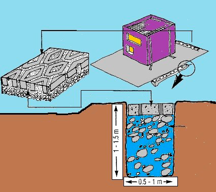
Therefore, a simple tried and tested alternate is proposed. This consists of Pre-Cast RCC Rings that are normally used in lining wells. The rings of 3 – 4 – or 5 feet diameter are stacked on each other to a specified height. The intervention has been displayed by me in the Akhter Hameed Khan National Center for Rural Development (NCRD) at Chak Shahzad, Islamabad, Pakistan. Here a series of plastered and un-plastered tanks demonstrate an affordable and quickly set up a tank that is more permanent and carries the added advantage of maintaining water temperature. This is not so in the case of polyethylene or fiberglass tanks where summer temperatures cause stored water to heat up to uncomfortable levels thus restricting use. Thirdly, the use of concrete is very common in the many parts of the Country in the shape of hollow and solid blocks. Gravel is available in plenty and sand is readily procured. Communities can be persuaded to prepare the rings themselves after training and construct them at conveniently located sites, thereby stimulating local economies. Transportation costs will be reduced and storage till erection will not be a problem.
Recharge Facility:
Alternative to storing, rainwater may be charged into the groundwater aquifers. This can be
done through any suitable structures like dug-wells, bore-wells, recharge trenches and recharge pits.
8.12 Methods of Harvesting Water:
There are two broad approaches to harvesting water:
1. Storing rainwater for direct use.
2. Recharging groundwater aquifers.
Storing Rainwater for Direct Use:
Rooftop harvesting has been practiced for ages, and even today it is practiced in many places throughout the world. In some cases, the rooftop harvesting system is a little more a split pipe or bamboo directing runoff from the roof into an old oil drum placed near the roof.
Generally, runoff from only paved surfaces is used for storing, since it is relatively free of bacteriological contamination. Drainpipes that collect water from the catchment (rooftop) are diverted to the storage container To prevent leaves and debris from entering the system, mesh filters should be provided at the mouth of the drain pipe. Further, a first-flush device should be provided in the conduit before it connects to the storage container. If the stored water is to be used for drinking purposes, a sand
filter should also be provided. A grill prevents debris from entering the drainpipe.
Coarse Mesh (Grill) prevents Passage of Debris.
An underground RCC/ Masonry Tank can be used for storage of the rainwater. The tank can be installed inside the basement of a building or outside the building. Pre-Cast, Concrete Rings used commonly for well lining and readily available in many parts of the Country, can be stacked to construct a tank and can be installed above the ground.
Each tank must have an overflow system for situations when excess water enters the tank. The overflow can be connected to the drainage system.
Design of Storage Tank:
The quantity of water stored in a water harvesting system depends on the size of the catchment area and the size of the storage tank. The storage tank has to be designed according to the water requirements, rainfall, and catchment availability.
First Flush Device:
A first-flush device is a valve or a simple device that is used to ensure that runoff from the first spell of rain is flushed out and does not enter the system. This needs to be done since the first spell of rain carries with it a relatively larger amount of pollutants from the air and catchment surface.
Design Parameters for Storage Tanks:
1. Average annual rainfall.
2. Size of the catchment.
3. Drinking water requirement.
Suppose the system has to be designed for meeting the drinking water requirement of a 5-member family living in a building with a rooftop area of 100 sq. m. The average annual rainfall in the region is 600 mm. The daily drinking water requirement per person (drinking and cooking) is 10 liters.
We shall first calculate the maximum amount of rainfall that can be harvested from the rooftop:
Following details are available:
Area of the catchment (A) = 100 sq. m.
Average annual rainfall (R) = 600 mm (0.61 m) Runoff coefficient (C) = 0.85
Annual water harvesting potential from 100 sq. m. roof = Ax R x C
= 100 × 0.6 × 0.85 = 51 cu. m. (51,000 liters)
The tank capacity has to be designed for the dry period, i.e., the period between the two consecutive rainy seasons. With a monsoon extending over four months, the dry season is of 245 days.
Drinking water requirement for the family (dry season) =245 × 5 × 10 = 12,250 liters
As a safety factor, the tank should be built 20 % larger than required, i.e., 14,700 liters. This tank can meet the basic drinking water requirement of a 5-member family for the dry period.
Runoff Coefficient:
Runoff coefficient is the factor that accounts for the fact that all the rainfall falling on a catchment cannot be collected. Some rainfall will be lost from the catchment by evaporation and retention on the surface itself.
Table: Runoff coefficients for various surfaces:21
Type of Catchment Coefficients
Roof Catchments
-Tiles 0.8 – 0.9
- Corrugated metal sheets 0.7 – 0.9
Ground surface coverings
- Concrete 0.6 – 0.8
- Brick pavement 0.5 – 0.6
Untreated ground catchments
➔ Soil on slopes less than 10 % 0.0 – 0.3
- Rocky natural catchments 0.2 – 0.5
Quality of Stored Water:
Rainwater collected from rooftops is free of mineral pollutants like fluoride and calcium salts, which are generally found in groundwater. But, it is likely to be contaminated with these types of pollutants.
1. Air pollutants.
2. Surface contamination (e.g., silt, dust).
Measures to Ensure Water Quality:
All these types of contamination can be prevented to a large extent by ensuring that the runoff from the first 20 mm of rainfall is flushed off.
Most of the debris carried by. the water from the rooftop i.e. leaves, plastic bags, and paper pieces is arrested by the grill net terrace outlet for rainwater. Remaining contaminants like silt and blow dirt can be removed by sedimentation (settlement), and filtration.
Contrary to popular belief, water quality improves overtime during storage in the tank because impurities settle in the tank if the water is not disturbed. Even pathogenic (harmful) organisms gradually die out due to storage.
Additionally, biological contamination can be removed by disinfecting the water. Many simple methods of disinfecting are available which can be done at a domestic level.22
Recharging Groundwater Aquifers:
In places where the withdrawal of water is more than the rate of recharge, an imbalance in the groundwater reserves are created. Recharging of aquifers are undertaken with the following objectives:
• To maintain or augment natural groundwater as an economic resource.
• To conserve excess surface water underground.
• To combat progressive depletion of groundwater levels.
• To combat unfavorable salt balance and saline water intrusion.
Design of an Aquifer Recharge System:
To achieve the objectives it is imperative to plan out an artificial recharge scheme in a scientific manner. Thus it is imperative that proper scientific investigations be carried out for the selection of a site for artificial recharge of groundwater.
The Proper Design Will Include the Following Considerations:
Selection of site: The Recharge structures should be planned out after conducting proper hydrogeological investigations. Based on the analysis of this data (already existing or those collected during the investigation) it should be possible to:
• Define the sub-surface geology.
• Determine the presence or absence of impermeable layers or lenses that can impede percolation.
• Define depths to the water table and groundwater flow directions.
• Establish the maximum rate of recharge that could be achieved at the site.
21 Source: Pacey, Arnold and Cullis, Adrian 1989, Rainwater Harvesting: The collection of rainfall and runoff in rural areas. Intermediate Technology Publications. London, pg. 55
22 Specifications for drinking water are given by IS: 10500 and World Health Organization (WHO).
Source of Water Used for Recharge:
Basically, the potential of rainwater harvesting and the quantity and quality of water available for recharging, have to be assessed.
• Engineering, construction, and costs.
• Operation, maintenance, and monitoring.
Various kinds of recharge structures are possible which can ensure that rainwater percolates in the ground instead of draining away from the surface. While some structures promote the percolation of water through soil strata at a shallower depth (e.g., recharge trenches, permeable pavements), others conduct water to greater depths from where it joins the groundwater (e.g., recharge wells).
At many locations, existing features like wells, pits, and tanks can be modified to be used as recharge structures, eliminating the need to construct any structures afresh.
A few commonly used recharging methods are explained here. Innumerable innovations and combinations of these methods are possible.
Bore-Wells / Dug-Wells:
Rainwater that is collected on the rooftop of a building is diverted by drainpipes to a settlement or filtration tank, from which it flows into the recharge well (bore-well or dug-well).
If a bore-well is used for recharging, then the casing (outer pipe) of the bore-well should preferably be a slotted or perforated pipe so that more surface area is available for the water to percolate. Developing a bore-well would increase its recharging capacity (developing is the process where water or air is forced into the well under pressure to loosen the soil strata surrounding the bore to make it more permeable).
Recharge Bore-Well:
If a dug-well is used for recharge, the well lining should have openings (weep-holes) at regular intervals to allow the seepage of water through the sides. Dug-wells should be covered to prevent mosquito breeding and entry of leaves and debris. The bottom of the recharge dug-wells should be desilted annually to maintain the intake capacity.
Precautions should be taken to ensure that physical matter in the runoff like silt and floating debris do not enter the well since it may cause clogging of the recharge structure. It is preferred that the dug-well or bore-well used for recharging be shallower than the water table. This ensures that the water recharged through the well has a sufficient thickness of soil medium through which it has to pass before it joins the groundwater. Any old well which has become defunct can be used for recharging since the depth of such wells is above the water level.
Quality of Water Recharged:
The quality of water entering the recharging wells can be ensured by providing the following elements in the system:
1. Filter mesh at the entrance point of rooftop drains.
2. Settlement chamber.
3. Filter bed.
Settlement Tank:
Settlement tanks are used to remove silt and other floating impurities from rainwater. A settlement tank is like an ordinary storage container having provisions for inflow (bringing water from the catchment), outflow (carrying water to the recharge well), and overflow. A settlement tank can have an unpaved bottom surface to allow standing water to percolate into the soil.
Apart from removing silt from the water, the desilting chamber acts as a buffer in the system. In case of excess rainfall, the rate of recharge, especially of bore-wells, may not match the rate of rainfall. In such situations, the desilting chamber holds the excess amount of water till it is soaked up by the recharge structure.
Options for Settlement Tank.
Any container with an adequate capacity of storage can be used as a settlement tank. Generally, masonry or concrete underground tanks are preferred since they do not occupy any surface area. Old disused tanks can be modified to be used as settlement tanks
For overground tanks, pre-fabricated Concrete Rings or Ferro-Cement tanks can be used. Pre-fabricated tanks are easy to install.
Design Parameters for Settlement Tank
For designing the optimum capacity of the tank, the following aspects have to be considered:
1. Size of the catchment
2. Intensity of rainfall
3. Rate of recharge
Since the desilting tank also acts as a buffer tank, it is designed such that it can retain a certain amount of rainfall, since the rate of recharge may not be comparable with the rate of runoff. The capacity of the tank should be enough to retain the runoff occurring from conditions of peak rainfall intensity based on a 25-year frequency. The rate of recharge in comparison to runoff is a critical factor.
However, since accurate recharge rates are not available without detailed geo-hydrological studies, the rates have to be assumed. The capacity of the recharge tank is designed to retain runoff from at least 15 minutes of rainfall of peak intensity.
Suppose the following data is available:
Area of rooftop catchment (A) = 100 sq. m.
Peak rainfall in 15 min (r) = 25 mm (0.025 m)
Runoff coefficient (C) = 0.85
= A x r x C
= 100 × 0.025 × 0.85
= 2.125 cu. m. (2,125 liters).
Then, the capacity of the desilting tank = 2,500 Liters.
Recharge Pits.
A recharge pit is a pit 1.5 m to 3 m wide and 2 m to 3 m deep. The excavated pit is lined with a brick/stone wall with openings (weep-holes) at regular intervals. The top area of the pit can be covered with a perforated cover. The method for designing a recharge pit is similar to that for a settlement tank.
Soak Aways:
A Soakaway is a bored hole of up to 30 cm diameter drilled in the ground to a depth of 3 to 5m. The Soakaway can be drilled with a manual auger unless hard rock is found at a shallow depth.
The borehole can be left unlined if a stable soil formation like clay is present. In such cases, the Soak away may be filled up with media like brickbats. In unstable formations like sand, the Soak away should be lined with a Pre-cast Cement Rings to prevent collapse.
A small sump is built at the top end of the Soakaway where some amount of runoff can be retained before it Infiltrates through the soakaway. Since the sump also acts as a buffer in the system, it has to be designed on the basis of expected runoff as described for settlement tanks.
Simple; Low-Cost Surface Rain Water Harvesting.
A Geomembrane Lining with Mazri (Date Palm Foliage Sindh/ Baluchistan) Cover would be of great advantage. This is a self-help Project and can be augmented with the Provision of appropriate Geomembrane.

Surface Water Harvesting Pre-Cast Concrete Rings; GI Cover, 2” Faucet.
Terraced Area: Mung, Haripur, Hazara.
Recharge Trenches:
Recharging through recharge trenches, recharge pits and Soakaways is simpler compared to recharge through wells. Fewer precautions have to be taken to maintain the quality of the rainfall-runoff. For these types of structures, there is no restriction on the type of catchment from which water is to be harvested, i.e., both paved and unpaved catchments can be tapped. A recharge trench is simply a continuous trench excavated in the ground and refilled with porous media like pebbles, boulders.
Design of a Recharge Trench:
The methodology of the design of a recharge trench is similar to that for designing a settlement tank. The difference is that the water-holding capacity of a recharge trench is less than its gross volume because it is filled with a porous material. A factor of the loose density of the media (void ratio) has to be applied to the equation. The void ratio of the filler material varies with the kind of material used, but for commonly used materials like brickbats, pebbles, and gravel, a void ratio of 0.5 may be assumed. Using the same method as used for designing a settlement tank:
Assuming a void ratio of 0.5, the required capacity of a recharge tank
= (100 × 0.025 × 0.85)/ 0.5
= 4.25 m3 (4,250 liters).
In designing a recharge trench, the length of the trench is an important factor. Once the required capacity is calculated, length can be calculated by considering a fixed depth and width.23
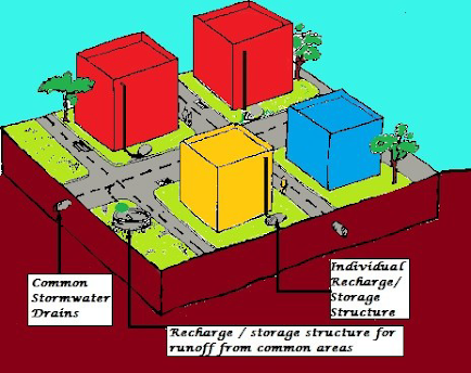
Community Level Water Harvesting System.
Tapping stormwater drains in a community-level system is another option as opposed to single home water harvesting units. In this System the entire Community, along with common land is tapped for Water Harvesting, thereby increasing the Net Gain corresponding to the size of catchment. To control the total amount of runoff received by a large scale system, the catchment can be subdivided into smaller parts. A locality-level water harvesting system illustrated in the figure below shows how the runoff from individual houses can be dealt with at the building-level itself, while remaining runoff from the stormwater drain (which drains water from roads and open areas) can be harvested by constructing recharge structures in common areas.
23 http://www.rainwaterharvesting.org/urban/Design_Recharge.htm
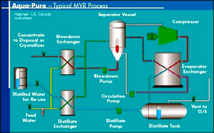
Water Distillation:
Aqua-Pure Evaporator/ Crystallizer System design takes advantage of the most recent innovations in heat exchanger technology, incorporating a compact state-of-the-art plate re-boiler exchanger that utilizes very low approach temperatures and high re-boiler brine flow rates, maximizing the thermal transfer efficiency while minimizing fouling tendencies.
Pre-manufactured compact modules range in capacity from 10usgpm to 400usgpm and can be moved from site to site.
Systems recover 97% of the energy required to distill water (<25 BTU/ lb wastewater feed). This results in very low energy consumption, typically 60-70kW/ 1000usg of wastewater feed.
Powered from conventional electricity, steam, or waste energy. Evaporators are designed to handle wastewater with varying influent characteristics while maintaining consistently high quality distilled water output.
Configurations include:
Mechanical Vapour Recompression (MVR), Thermo Vapour
Recompression (TVR), Multiple Effect (ME), or a combination.
Zero Liquid Discharge (ZLD) Solutions.
Swenson’s crystallizer expertise allows Aqua-Pure to offer ZLD solutions for our customers. Where required, a Reverse Osmosis (RO) membrane or other system may be supplied ahead of the evaporator system.
Water Retention:
Retention of water for brief periods to either meet immediate needs or allow infiltration into the ground as opposed to Mega Dams is a desirable objective. Firstly it is necessary that we understand the Water cycles.
Mega Dams.
Geology and water in rock masses can be major sources of problems in dam safety. Water seeping in rock masses can affect the safety of dams in essentially two ways: erosion and uplift.
Several dam failures have been attributed to excessive uplift. Earthquakes can be induced by dams. Globally, there are over 100 identified cases of earthquakes that scientists believe were triggered by reservoirs. The most serious case may be the 7.9-magnitude Sichuan earthquake in May 2008, which killed an estimated 80,000 people and has been linked to the construction of the Zipingpu Dam.
Reservoir-Induced Seismicity (RIS):
The most widely accepted explanation of how dams cause earthquakes is related to the extra water pressure created in the micro-cracks and fissures in the ground under and near a reservoir. When the pressure of the water in the rocks increases, it acts to lubricate faults which are already under tectonic strain but are prevented from slipping by the friction of the rock surfaces."
Given that every dam site has unique geological characteristics, it is not possible to accurately predict when and where earthquakes will occur. However, the International Commission on Large Dams recommends that RIS should be considered for reservoirs deeper than 100 meters.
• Depth of the reservoir is the most important factor, but the volume of water also plays a significant role in triggering earthquakes.
• RIS can be immediately noticed during filling periods of reservoirs.
• RIS can happen immediately after the filling of a reservoir or after a certain time lag.
Many dams are being built in seismically active regions, including the Himalayas, Southwest China, Iran, Turkey, and Chile. International Rivers calls for a moratorium on the construction of high dams in earthquake-prone areas.
The South Asian river basins, most of which have their source in the Himalayas, support rich ecosystems and irrigate millions of hectares of fields, thereby supporting some of the highest population
densities in the world.
Rivers are, however, also a source of conflict between countries and people in the region. The question of whether and how to harness rivers for hydropower generation and commercial irrigation is an issue of great concern and a source of controversy. Large-scale water development schemes have in the past contributed to the impoverishment of many river basin communities in South Asia.
However, many governments in the region exaggerate the irrigation and power benefits of large dams and neglect their social, environmental, and economic costs, and continue to promote them as the best option for increasing access to energy and water. Better ways to harness water and generate energy are too often overlooked. Decentralized renewable power supply options, such as off-grid micro-hydropower, biogas plants, solar and wind power – would often be more cost-effective and better suited to supply rural villages with electricity. Supporting poor farmers to trap rain when and where it falls would often be a better investment for rural poverty reduction than the construction of large storage dams.
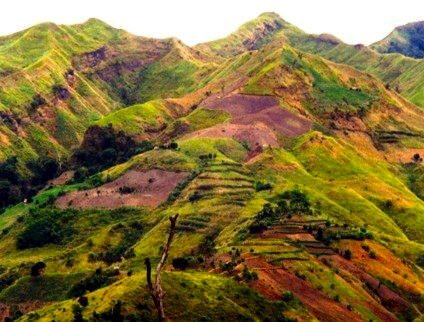
Our warming climate is changing the Himalayas faster than any other region of the world. The mountains’ mighty glaciers, the source of most large Asian rivers, are melting. Against these dramatic changes, the governments of India, Pakistan, Nepal, and Bhutan are planning to transform the Himalayan rivers into the powerhouse of South Asia. They want to build hundreds of Mega Dams to
generate electricity from the wild waters of the Himalayas.
The dams’ reservoirs and transmission lines will destroy thousands of houses, towns, villages, fields, spiritual sites, and even parts of the highest highway in the world, the Karakoram highway. Technically, run-of-river projects are projects without any storage or pondage. They use the flow of the water in the natural river course, or sometimes through diversions like canals and tunnels, to generate electricity.
They can have many of the typical structures such as dams, weirs, headraces, tailraces, and diversions tunnels. Many Himalayan dams are being classified as the run of river and hence are touted as socially and environmentally benign; this is false. Many run-of-river projects can have serious impacts by disturbing downstream river flows. Some run-of-river projects divert the water into tunnels, leaving downstream sections dry, and thus cause even more severe impacts downstream. Ecological Impacts The Himalayas are recognized as a hotspot of biodiversity.
With a reduction in force of impact of raindrops and soil that is bound with strong roots the process of infiltration of water into the soil is greatly increased. Reduction in wind speed also reduces erosion of soil, thus we not only prevent the erosion of precious topsoil we also gain in water. Ruthless cutting of our Forests has led to decreased infiltration of water and increased soil erosion.

Trees and Afforestation:
Forests occupy a relatively small proportion of the land area in Pakistan (some 3 – 5 %) but nevertheless play a vital role in the country’s economy. Forests remain an important source of fuelwood, grazing land, livelihood, and Government Revenue. Forests also provide multiple ecological services such as watershed protection, soil conservation, biodiversity habitat, and play a vital role in assuring Eco-system resilience (i.e. stability).
The Natural Forest Resource Assessment NFRA classification shows that forest cover is declining in Pakistan.24 Estimated deforestation rate over the 1990-2005 period was 2.1 % or 47 thousand hectares annually. Forest types included in this definition of forests are coniferous forest, riverain, and mangrove forest. It is estimated that the most valuable coniferous forest is declining at the rate of 40,000 hectares annually. Northern Areas and KP have the highest annual rates of deforestation (about 34,000 hectares in Northern Areas and 8,000 hectares in KP). Riverain and mangrove forests are also decreasing at the rate of 2,300 and 4,900 hectares annually. This is an alarming rate given the quite high ecological value of these types of forest Using this classification, the estimated costs of deforestation in Pakistan are between Rs. 206 to 334 million per anum.25
24 NFRA 2004
Forest Eco-System Protection: Economy Generation.
It is, by now, a well-known fact that trees and Forests are the foundation upon which the entire world of renewable natural resources is balanced Man . has interfered in the Natural Forest Eco-System in many ways. Clear cutting and reduction in the forest canopy are the most blatant means of interference. When these activities are curtailed, other less obvious means are used. Removal of forest litter is perhaps the most damaging. This is the first level of the forest food chain. Secondly, it forms the natural habitat for microorganisms that are essential to the dynamics of the ecological cycle. Upland, stony soils have a very slow weathering process and hydro-thermic cycle. With a reduction in the forest canopy, impaction and erosion capacity of raindrops are greatly increased. The absence of an under-story, as found in mixed tree and bush forests, further compounds this situation. The velocity of falling raindrops is curtailed as they strike the trees and filter down to the forest floor. If this does not happen, the soil is struck with higher velocity raindrops and is subject to movement on the surface. Waterbearing particles of soil are aided in erosion capacity. These soil particles act like tiny blades to further erode the nutrient-rich topsoil. Thus even the tertiary-source of nutrients is removed The sources of forest nutrition are:
• Forest Litter that decomposes into Humus.
• Symbiotic bacteria/ micro-organisms/ fungi that fix nitrogen.
• Mineralized topsoil (subjected to weathering).
• Transport of minerals within soil profile (no profile - no transport).
Thus it is obvious that our forest Eco-Systems have been destabilized (preservation of nutrients/ minerals circulated within the soil - vegetation subsystem).
Depleted forest resources with reduced canopy cover and malnourished trees with stunted growth do not serve the purpose that Nature intended them for. Also, natural regeneration and young sapling are the first to suffer. Thus the future of the forest is even bleaker than the present. Rank exploitation of timber resources in a non-sustainable way is the primary cause. However, the populations that live in close proximity to forests have a right to natural resources. They have needs for:
• Fuelwood.
• Fodder
• Building material.
• Income generation.
How is it possible to deny them access to these resources? Motivation by pointing out that it takes years to rebuild nutrient cycling and the attendant harmful effects upon the environment of deforestation are not sufficient to achieve forest protection. Alternates that are viable, cost-effective, and practicable are called for. The question arises do they exist? The answer is a resounding YES!
Seabuckthorn:
"Seabuckthorn is a deciduous shrub and is widely distributed throughout the temperate zones of Asia and Europe and throughout the subtropical zones of Asia at high altitudes."25 The Latin name Hippohae spp. Is used for this shrub that consists of six species and ten subspecies. It thrives from the sea level to 5,200 m. The annual coverage temperature is 0° C to 12° C, though it can survive temperatures as high as 40° C. Minimum temperature tolerance is as low as - 40° C. Annualprecipitation range requirement is 600 to 700 mm as most suitable. Precipitation of300 to 1,000 mm range is acceptable. Soil requirements are well-drained, sandy, or stony soils with a soil pH range of 5.5 to 8.3. Salinity of 1.1 % can be tolerated by the plants.
The plant has a very strong root system with a taproot of 3 m and horizontal roots of 6 to 10 m. Self-propagation through root turions enables the plant to produce 10 to 20 generations. The fruit of this plant contains 60 to 80 % juice. This juice has 200 to 1500 mg per 100 g and is rich in vitamins, sugar organic acids, and amino acids. The fruit contains 3 to 5% pulp oil and 8 to 18 % seed oil, rich in unsaturated acids, B- carotene, and vitamin E. The leaves contain 11 to 22 % crude protein, 3 to 6 % crude fat, and some flavonoids. The fruit can be used to make soft drinks health, food, medicines, and cosmetics
China has a Seabuckthorn Industry with over 100 factories producing over 200 products with a gross value of about US$ 40 million annually. The leaves and tender branches are excellent fodder for sheep, goats, and cattle. In China, 51 species of birds and 29 species of animals are dependent upon this plant as a part of their food chain. Some major benefits of this plant additionally exist. These are:26
• Nitrogen Fixing Capacity: An 8 to 10-year-old Seabuckthorn Forest can fix 180 Kg of nitrogen/ha/year (72 Kg/acre/year or 9Kg/Kanal/year).
• Biomass Production: A 6-year-old Seabuckthorn plantation can produce 18 tons of fuel-wood per hectare. Heat value is 4785.5 calories/ Kg. One ton of wood is equal to 0 68 tons of stand.ard coal
• Erosion Control: In comparison to wasteland a 7-year-old plantation can reduce 99 %runoff and 96 % soil loss.
• Soil Fertility: Nitrogen, phosphorus, and organic contents of soil are greatly increased.
• Companion Tree Growth: Pine and Popular when mixed with Seabuckthorn thrive due to nitrogen fixation and protection from the cover. Chinese results indicate that mixed stands of Pine and Seabuckthorn have 1.3 to 1.7 times higher growth rate.27
• Other Uses: Windbreaks and stream/ riverbank stabilization can be obtained.
Seabuckthorn is propagated from:
• Seed (germination rate 80 to 95 % - 1 Kg seed produces 104 to 133 thousand saplings).
• Hardwood Cuttings: 2-3-year-old shoots, rooting rate is 50 to 70 %.• Softwood Cuttings: & to 10 cm cuttings with several leaves are used and propagated in plastic film houses for 2 years.
• Aerial Seeding: 400 mm rainfall and 6 to 8 days of continuous cloudy and rainy days are required. At germination rates of 1 %, a density of 1 plant per 10 square meters is used. Pre-germination of seed treated with Natural Rooting and Fruiting Hormones are recommended
25 .Feasibility Study of Seabuckthorn Development in Pakistan, Lu Rongsen, ICIMOD (Nepal), MINFAL (Pakistan) 1996.
26 . Dr Abdul Wahid Jas , ra NADR, I NARC, Islamabad .
27. Chinese Success Models of Seabuckthorn Development, A Tour Report, Dr. A.W Jasra NADRI 1996.
Objections:
The unfortunate experiences of Eucalyptus and Wild Mulberry have raised fears of Invasive Species in the minds of many Foresters and NRM specialists. Along with resistance to change, this is causing a delay in the establishment of this plant. To ally some of these fears it is pointed out that Seabuckthorn is a native of Pakistan variety that flourishes here is Hippopchae rhamnoides (turkestanica) This sub-species is suited to arid hot summers and cold winters. About 3,000 hectares of wild Seabuckthorn Forests exist in Baltistan, Gilgit, Chitral, and Swat at altitudes between 2200 to 2800 m. At present afforestation has been carried out in Balochistan and Waziristan (Former FATA).

Comparison.
Having assessed the costs of degradation in Pakistan it is instructive to compare the overall environmental performance with other countries. A number of environmental sustainability indices have been developed to facilitate this process. The most comprehensive and widely quoted measure is the Environmental Sustainability Index (ESI), ESI is a composite index of 21 indicators that cover five broad categories of environmental pressure. The sub-components measure performance in the following areas:28
1. Environmental Systems.
2. Reducing Environmental Stresses.
3. Reducing Human Vulnerability to Environmental Stresses
4. Societal and Institutional Capacity to Respond to Environmental Challenges.
5. Global Stewardship.
As with any other aggregate index, the ESI is not without its shortcomings. Given the lack of information in many countries, the rankings are an approximation of sustainability, based on an aggregation of a wide array of indicators. As a result of high population density, a pollution-intensive industrial structure, a vulnerable natural resource base, and limited capacity to mitigate environmental stress, Pakistan scores the lowest ESI in South Asia.
Pakistan remains relatively more susceptible to land degradation than most nations in the arid zone category. This vulnerability reflects not only the Country’s water scarcity, but it’s ability to cope
with the problem.
28 Global Stewardship. a collaborative venture of the Yale Center of Environmental Law and Policy and CIESIN at Columbia University.
29 Document of the World Bank Report No. 36946-PK Pakistan Strategic Country Environmental Assessment. South Asia Environment and Social Development Unit South Asia Region August 21, 2006.
The loss of forest cover and conversion of forested land to other uses can degrade supplies of freshwater, threatening the survival of millions of people and damaging the environment.30 Watershed conditions can be best improved if forests are managed with human as well as hydrological goals as a priority. Watershed degradation has been recognized in many countries as a serious threat to the environment and to the survival of people living in watershed and downstream areas over the past 20 years. Watershed Management Programs failed to achieve their goals, the study says, because they neglected to consider the needs and behaviors of human beings and instead focused only on conservation aspects of natural resources.
The lack of long term commitment to address underlying causes of forest and watershed degradation also contributed to the failures. Mountainous forested watersheds are the most important freshwater yielding areas in the world, the study says, but they are also the source areas for landslides, torrents and floods."
To prevent or lessen disasters in mountainous terrain, healthy forest cover must be maintained on watersheds that are subject to torrential rainfall. The FAO recommends the development of programs that combine forest protection with zoning, floodplain management and engineering structures to protect people from landslides, debris flows and floods.
The largest and most damaging floods in major rivers are not affected by the extent of watershed forest cover, the agency says, but moderate and localized floods can increase when forests are removed. Healthy upland and riparian forests can keep high levels of sediment from being deposited in rivers, lakes and reservoirs during floods.
The economic value of water must be recognized, the FAO states, and recommends "reducing water subsidies and treating water as a commodity rather than a free good" so that economic incentives can support better watershed management. With economic incentives in place, new management techniques can be attempted, the agency says, such as replacing trees that consume a great deal of water with species that consume less when forests in municipal watersheds are thinned or logged.
Throughout its forests and freshwater report, the FAO team emphasizes enhanced communication with local communities and stakeholders, expanded educational and training programs, and sharing of effective techniques with local residents to increase the conservation of forested watersheds.
30 FAO: Fresh Water Supplies Depend on Healthy Forests.
Watershed Management.
The Four Core Principles of Watershed Management:
1. Watersheds are natural systems that we can work with.
2. Watershed management is continuous and needs a multidisciplinary approach.
3. A watershed management framework supports partnering, using sound science, taking well-planned actions, and achieving results.
4. A flexible approach is always needed.
A watershed management plan should include an overview of the current conditions of the watershed, including physical, chemical, and biological characteristics of the stream network, as well as current land use and potential sources of impairment. The plan will outline the goals of the management plan. These goals will quantify the level of impairment. Next, a plan will provide management strategies through which the impairments will be addressed.
Finally, it will include a time-line for completing watershed management implementation to take place and an estimate of how much the plan will cost to implement.
Define Watershed Plan.
Defining a watershed plan deals with preliminary activities you undertake to start scoping out your planning effort. It includes information on defining issues of concern, developing preliminary goals, and identifying indicators to assess current conditions.
The user can work with the Digital Watershed tool to identify both the geographic region in which their plan will focus and the impairments present in their watershed.
Gather Existing Data. Gathering existing data is the first step in watershed characterization. It includes the collection of information from existing reports and data sets. Users can work with the Digital Watershed Tool to help them identify available data, locate the information, gather and organize necessary data, and determine data needs.
Assess Watershed Conditions ( ATtILA, ReVA). Once all of the existing watershed data has been gathered, the next step is to assess watershed conditions. Assessing watershed conditions will help a user to determine the acceptability of data, identify data gaps, and design a future sampling plan. The user can work with the ATtILA tool to determine land use characteristics and to calculate the number of impervious surfaces in a specific watershed. The user will also work with the ReVA tool to identify potential landscape stressors in their watershed.
Tools that have been developed include the Automated Geospatial Watershed Assessment (AGWA) tool and the Analytical Tools Interface for Landscape Assessments (ATtILA):
• The AGWA tool helps identify and prioritize potential problem areas at the watershed level.
It can evaluate the effects of various land-use changes on water quality and identify locations where impacts are likely to be most significant. Model outputs for streams and upland areas (above the streamside or riparian corridor) can be quantified and mapped for comparison with other data and assessment results. AGWA incorporates two watershed runoff models, the Runoff and Erosion Model (KINEROS2) and the Soil and Water Assessment Tool (SWAT)—into GIS.
ATtILA is a Downloadable ArcView extension that calculates landscape characteristics, riparian characteristics, human stressors, and physical characteristics for a given area using simple, easily accessible data. Digital Watershed provides static layers containing statistics/characteristics for 8 digit watersheds in Digital Watershed, as well as a web-interface to run ATtILA over the web to generate up-to-date summary statistics.

• ATtILA is a user-friendly GIS extension that calculates many common landscape metrics. It is equally suitable across all landscapes, from deserts and forests to urban areas. ATtILA measures four types of characteristics:
o Landscape characteristics, e.g. percentage of grassland cover or number and size of grassland patches
o Riparian characteristics, which describe the land adjacent to or near streams
o Human activity characteristics, such as population increases, road building, and land-use practices.
o Physical characteristics, which provide statistical summaries of attributes such as elevation and slope.
Regional Vulnerability Assessment (ReVA).
ReVA is a risk assessment tool that uses physical, political, and socio-economic parameters of 8-digit
watersheds to assess the overall vulnerability or stress on its natural resources. These parameters are
presented as statistics and can be used to describe the risk of impairment due to resource management,
invasive species, land cover change, or overall non-point source pollution.
Watershed management and assessment requires an interdisciplinary approach to a complex problem. Comprehensive GIS inventories of the natural and built environment provide watershed managers with the data, tools, and techniques to manage the complexities of watersheds. The tools of GIS and spatial analysis allow decision-makers and citizens to understand and visualize the many features of a watershed, from land-use patterns to species diversity to flood-hazard areas. The powerful spatial analytic features of the ArcGIS system, combined with increasingly available high-quality digital data, should prove of great benefit to all concerned with managing the complex ecological, biological, economic, and political systems involved in a watershed.
Flood hazard mitigation is one of the purposes of a comprehensive watershed inventory. ArcGIS tools, combined with high-resolution digital orthophotography, provide an important tool in hazard mitigation planning.
Afforestation.
Hydromulch is a mixture of fertilizer, seed, shredded wood, and tackifier, a sticky substance that helps the mulch material cling to hillsides and steep slopes. The biodegradable hydro-mulch stabilizes the soil and provides nutrient media for new plant growth on fire-damaged lands, overcut areas for Reforestation, Planting New Forests, or for Soil Conservation. Rapid-response aerial hydro mulching and hydroseeding to mitigate problems and preserve a healthy landscape is the best way forward for severely depleted Reforestation or Afforestation. GPS technology ensures precision coverage and records flight patterns to show plantation. Both Helicopters and Fixed Wing Aircraft can be used for this operation.
Bio-Retention:
Swales: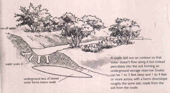
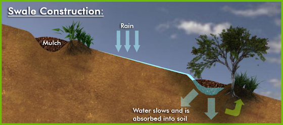
Swales or berms are ancient practices and have been used to control water flow for centuries. Swales are simply shallow, low depressions in the ground designed to encourage the accumulation of rain during storms and hold it for a few hours or days to let it infiltrate into the soil. Swales ideally are tree-lined and store water for the immediate landscape as well as help cleanse the water as it percolates into the aquifer. Swales can be installed separately or as part of a larger rainwater catchment system with rain gardens, cisterns, and other water conservation measures.
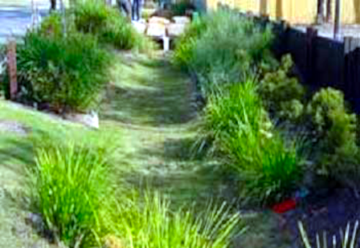
Swales are one of the cheapest and easiest water storage methods and can be installed almost anywhere. If properly built they greatly reduce storm runoff; thereby reducing the impact of storms on local storm runoff systems. But more importantly, they catch and preserve fresh rain where it can be used by your shrubs and trees. Swales are an easy solution that can be effective in homes, commercial buildings, and street mediums in place of curbs.
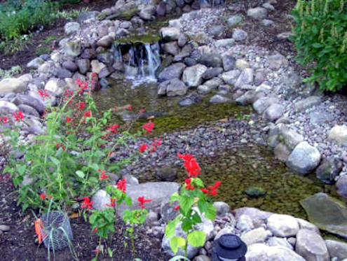
Berms:
Berms are raised beds that can be used to direct water to swales. They are the equivalent of the slope in the road used to push water off the middle of the road toward the curbs. Ideally, berms and swales should be designed into the landscape where there is any noticeable slope to slow and capture runoff. They can be part of the site plan for an individual home or integrated into the design of an entire multiunit complex or subdivision development.
Real Benefits:
Recent research has documented the stormwater quality benefits from swales and low-lying areas by reducing the flow and allowing slower infiltration into the groundwater system. This is a finding which past generations were aware of. In our hurry to pave the world with concrete, we threw our knowledge of swales and berms out with the stormwater. It is best to preserve low-lying areas such as wetlands and swales. These low-lying areas retain stormwater, provide water quality filtration, and may allow for some infiltration to replenish groundwater supplies.
Swales can either be grassed, gravel, or rock. All designed to slow and retain the flow of runoff. They can also be used instead of costly curbs and gutters.
Residential development can be designed to adopt conservation measures to reduce runoff rates and volumes and to reduce pollutant loads. Stormwater is routed into swales, rather than storm sewers. The swales provide initial stormwater treatment, primarily infiltration and control sedimentation. The prairies diffuse the water and soils retain contaminants, slowing stormwater velocity.

If 60 % of the land is devoted to open spaces, residents can employ rain gardens and expect to retain 65 % of its stormwater on-site and reduce nutrient and heavy metal pollutants by 85 to 100 %. Maintenance costs for stormwater controls are expected to drop, downstream conditions improve and there is less flooding. A sign of success can be thriving populations of native fish in the artificially created lakes.
Key Elements Considerations:
Key elements to consider when building a swale include:
• Swales are not intended to move water but to hold water for soil absorption.
• The width of the swale should be covered by the crown of the mature surrounding trees.
• Soil in the swale should not be compacted or sealed but should be loose to encourage absorption.
One tree can reduce stormwater runoff by 4,000 gallons a year thus greatly reducing the need to build costly water treatment plants. So swales lined with native trees are an extremely cost-effective, and often overlooked low-tech, water conservation technique. Swales with the proper plants and trees help manage runoff and make water healthy for people, nature, and fish and are a low-cost, win-win solution.31
31 http://www.harvesth2o.com/swales.shtml
Rain Water Gardens:
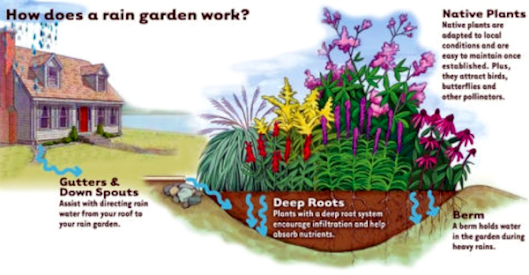
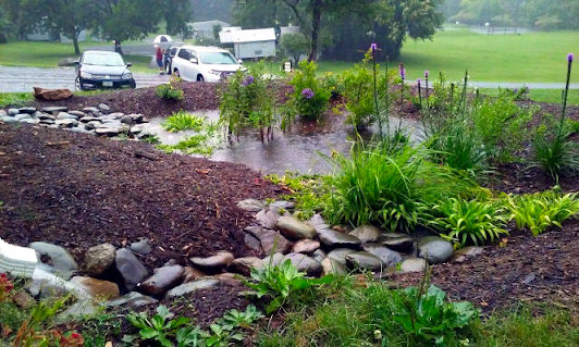
A rain garden is a depressed area in the landscape that collects rainwater from a roof, driveway, or street and allows it to soak into the ground. Planted with grasses and flowering perennials, rain gardens can be a cost-effective and beautiful way to reduce runoff from your property. Rain gardens can also help filter out pollutants in runoff and provide food and shelter for butterflies, songbirds, and other wildlife. More complex rain gardens with drainage systems and amended soils are often referred to as Bioretention.32
During a downpour in many Municipalities, water gushes out of downspouts, across lawns treated with pesticides and fertilizers, onto oily streets, and, finally, down a storm drain that dumps that pollution along with the water into a stream, river, or bay. By building a rain garden, gutter water can be diverted into an attractive planting bed that works like a sponge and natural filter to clean the water and let it percolate slowly into the surrounding soil.
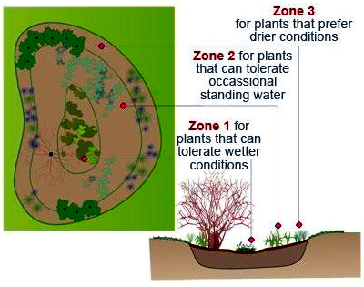
The plants and amended soil in a rain garden work together to filter runoff. Generally, a rain garden is comprised of three zones that correspond to the tolerance plants have to standing water; the better a plant can handle "wet feet," the closer it is placed to the center of the garden. Whenever possible, shop for native and drought-tolerant plants, keeping in mind that parts of a rain garden remain wet for long periods of time, while others are drier. Zone 1, the centermost ring of the rain garden, should be stocked with plants that like standing water for long periods of time. The middle ring, Zone 2, should have plants that can tolerate occasional standing water. The outermost ring, Zone 3, is rarely wet for any length of time and is best planted with species that prefer drier climates. 33

32 https://www.epa.gov/soakuptherain/soak-rain-rain-gardens
33 https://www.thisoldhouse.com/how-to/how-to-build-rain-garden-to-filter-run
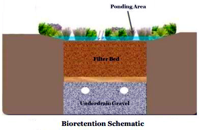
The way a Bioretention Facility works is that stormwater flows into it and temporarily ponds on the surface in the ponding area. Water then slowly filters through the filter bed (or media layer) where it may be collected by the underdrain (a perforated pipe beneath the filter bed) and conveyed to the storm sewer system. Not all bioretention practices are designed to have an underdrain, in areas of “good” soils (soils that meet a specific infiltration capacity) practice can be designed to allow the water to infiltrate into the underlying soils.
Vegetation is a very important component of a bioretention system. As stormwater makes its way through the practice, it is taken up and utilized by the vegetation along with the corresponding nutrients. The Figure below demonstrates how runoff makes its way through the bioretention area.
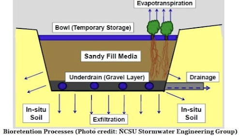
Runoff Reduction and Pollutant Removal:
Runoff reduction is defined as the total volume of water reduced through canopy interception, soil infiltration, evaporation, rainfall harvesting, engineered infiltration, extended filtration or evapotranspiration. The runoff reduction associated with a bioretention practice ranges anywhere from
40-80% (CWP and CSN, 2008).
Pollutant removal is accomplished via processes such as settling, filtering, adsorption, biological uptake, and denitrification. The range of pollutant removal efficiencies for Total Nitrogen (TN), Total Phosphorus (TP) and Total Suspended Solids (TSS) can be seen in the Table below.

The pollutant removal rate of a particular bioretention area can be increased or decreased based on the design components and what pollutant(s) is being targeted for reduction.
A bioretention area can vary in how it is designed. Some design variations include using an underdrain in the stone layer to slowly dewater the area, sending remaining runoff back to the storm sewer system, or creating a sump at the bottom of the area in the stone layer where water will infiltrate into the surrounding soils within 48 hours.
In addition, it is also possible to design the bioretention area so as to meet specific pollutant removal needs. For example, by creating a sump at the bottom of the area, one can achieve enhanced nitrogen removal. These different design variations are illustrated in the Table below.
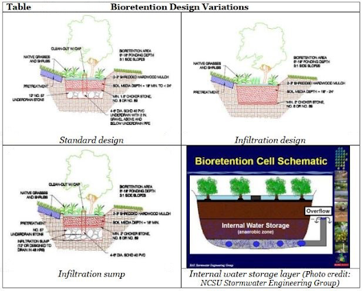
Water leaves the bioretention area through several different means. It can evaporate from the ponding area, be taken-up and utilized, or evapo-transpired by the vegetation, or infiltrated into the surrounding soils. In addition, most Bioretention areas are designed to have a designated outlet structure of some kind. Outlet structures can take many different forms and oftentimes depend on the design of the facility. One type of outlet or overflow structure that is often used is an inlet structure that is placed at the maximum design ponding depth so as to allow for a bypass of larger stormwater volumes out of the facility. Another is a riser structure that accepts water that exceeds the maximum ponding depth and conveys it to the underground storm drain pipes.
Underdrains are another way that runoff can leave the bioretention. Underdrains either convey water to the existing storm drain or daylight into an above-ground swale, woodland, or stream. It is important to know where the underdrains connect to, so you can inspect the outlet. They commonly have clean-out and observation well pipes that surface at pipe intersections. Underdrains are used in environments where the soil conditions make it difficult to infiltrate water into the surrounding area. Underdrains are also useful in situations where the runoff entering the practice is contaminated from the contributing drainage area (called Hotspots) and so cannot be infiltrated into the surrounding soils due to potential groundwater contamination. The Table below shows several different types of outlet structures commonly used for Bioretention.
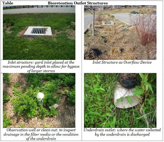
Pretreatment.
This is necessary to trap sediment and debris before it reaches and clogs the filter bed.There are several different types of pretreatment measures that are used to protect bioretention.
Examples can be found in the Table below.
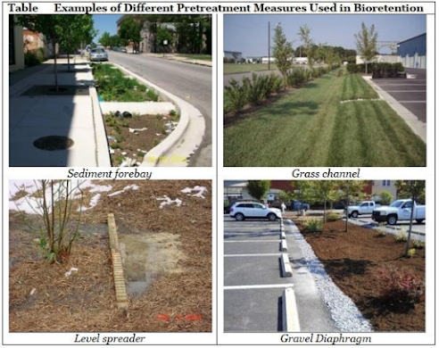
Vegetation.
Vegetation is an essential component of any bioretention area. As was noted earlier, vegetation is responsible for a significant portion of the pollutant removal and runoff reduction of this stormwater practice. The landscape regime of a bioretention area is often determined by the amount of maintenance it will receive. Often, this is a function of the visibility of the practice. If the practice will be infrequently maintained, then hardy plant materials should be specified at the various planting zones in the facility. If an owner will have the bioretention area maintained as part of the regular maintenance activities (e.g., grass cutting, weeding, etc) then perhaps a more perennial garden is suitable. One of the most costly aspects of bioretention maintenance is the cost of supplementing or replacing mulch if it is specified. Accordingly, careful selection of a diverse plant palette that includes herbaceous material such as ground covers in lieu of widely spaced woody species can result in a reduction in maintenance costs.
Another important factor to consider in designing the landscaping regime of the bioretention is the dynamic nature of vegetation. Typically designers specify material for the immediate conditions. However the systems evolve as the vegetation grows. For example, as trees and shrubs mature, the system might be transformed from a sunny bioretention to having more shade under trees. Oftentimes, it is beneficial to conduct a plant evaluation specified time increments (i.e., 3 year, 6 year, 9 year and so on) to evaluate the suitability of the plant regime and the appropriateness of the plant material.34 The Table below demonstrates four different typical landscaping regimes for bioretention.
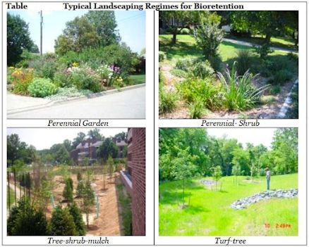
Step by step instructions for Constructing; Planting and Maintaining the Bioretention Interventions are provided in the cited Article.35
We need to learn basic visual indicators to quickly identify and diagnose maintenance problems that prevent it from functioning properly. Methods for visually inspecting bioretention through all stages of its life cycle and Measures for Maintenance are equally important.
34 Gillette, 2013.
35 CSN TECHNICAL BULLETIN No. 10 Bioretention Illustrated: “A Visual Guide for Constructing, Inspecting, Maintaining and Verifying the Bioretention Practice Version 2.0 October 20, 2013.http://chesapeakestormwater.net/wp-content/uploads/downloads/2013/10/FINAL-VERSION-BIORETENTION-ILLUSTRATED-102113.pdf Prepared by: Ted Scott Stormwater Maintenance & Consulting, Cecilia Lane & Tom Schueler Chesapeake Stormwater Network.
Irrigation:
Introduction:
Water is proving to be a precious and increasingly unavailable resource. The importance of water for our continued existence cannot be denied. While it is not necessary to belabor the point some alternate strategies are outlined below to provide some relief to the masses. This paper is primarily intended for the efficient use of water in the Agricultural/ Horticultural Sector. I have taken the term “Conservation Irrigation” to include source; extraction, delivery, and replenishment. The source will include surface and groundwater, harnessing, and development. This will also include survey and pollution control. Extraction will cover energy-efficient means of harvesting and providing for use. This is primarily meant to reduce the per liter cost. The next stage is that of delivery. We are all aware of the tremendous losses incurred in this phase of water management. This factor will include low-cost conveyance and efficient means of application. The final aspect is that of replenishment, this is primarily concerned with the recharging of aquifers. Reforestation for natural recharging is dealt with separately. This is due to the pressure for immediate recharging and the long lead-time required for reestablishing natural charging. It is envisaged that using these strategies can affect tremendous savings. Both in terms of cost as well as liters used, to achieve even better results than being had at present. There is a lot of room for improvement and a scientific and responsible attitude has to be implemented at the earliest. Of course, all these factors entail costs. However, all efforts have been made to ensure that costs are kept to a bare minimum. In many cases, these costs will prove to less than what we are already expending in the present, wasteful manner of utilizing water. In any case, costs will have to be met in order to ensure continued existence!
Our current method of Flood Irrigation is the most wasteful method of applying water to crops and is susceptible to Evaporation and Leaching as well as the cause of Secondary Salinization/ Raising the Water Table to Water Logged levels. It takes applied fertilizers in solution form directly into the below-grade water rather than allowing root uptake.
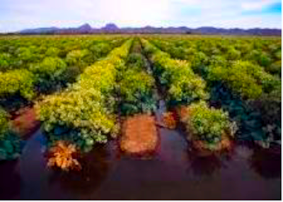
Conservation Irrigation.
Including sprinkle, drip, and subsurface (reticulation) irrigation has to be introduced and encouraged at all costs. Reforestation through Pre-Germination of forest trees seed doping with natural rooting and fruiting hormones and polymer coating along with Nutrients has to be resorted to.
This practice can be easily extended to Range Management. Given favorable rainfall, it is possible to establish large stands through aerial seeding. At present this practice is carried out at a 1% survival rate whereas the above-outlined method can increase survival to 40%. Community involvement to protect the seedlings from goats will have to be ensured. Conventional plantation by hand has to be encouraged through establishing Environment/ Predator Protected Nurseries that grow a mix of Farm Forest/ Fodder/ Timber and Fruit trees on a sustainable and commercial basis through Community Organizations; Sewage Treatment through the use of Bioaugmentation (addition of live bacteria to augment existing colonies) and Phytoremediation (use of plants and trees to uptake toxic elements) through the establishment of Reed Beds and Artificial Wetlands is seeing increasing use in developed Countries. Our weather conditions make this method, even more, cost-effective and efficient than those used in the Northern Latitudes; Water Harvesting including surface and rooftop harvesting has to be introduced and widely disseminated. Surface Water Harvesting can be used additionally as soil conservation structure for instance building of low-cost prefabricated cement ring tanks at gully heads; Aquifer Recharging; Alternate Energy Pumping; Water Recycling and supply of Potable Water are some of the options that have to be examined and adopted.
To conserve water resources and provide plants with water when needed in the required quantity only. Thus merely 10% of flood irrigation water will achieve better results. Conservation irrigation by means of Sprinklers, Drip or Sub-Soil are effective in conserving the amount of water expended while catering fully to the water needs of the plants.
Drip (Katra Paashi) & Sub-Soil (Reticulation) Irrigation (Zair eZameen Pashi):
Sub-soil and Drip irrigation is a slow watering process aimed at delivering water and essential, soluble nutrients directly to the root zone of a plant. Here evapotranspiration, plant requirements, and other losses are estimated and an attempt is made to match them. This is done at a rate that the soil will adsorb. Obviously, all this varies greatly with the type of plants, kind, and condition of the soil, and temperature.
However, efforts are made to keep the watering instructions as simple as possible. This is done by the provision of guides for various conditions. The object of this exercise is to maintain the water content of the soil close to its field capacity in order to ensure that the plant has optimum water with sufficient aeration. In all other irrigation systems there exist wet/ dry cycles. Secondly, there is no possibility of delivery at peak demand times. For example, when the sun is directly overhead between 11.00 am and 3.00 pm. During this period the droplets induced by sprinkle irrigation act like convex mirrors ad cause leaf burn by magnifying the intensity of the sun’s rays. Flood irrigation causes water heating and reflection of the sun’s rays onto the plant’s foliage. Early morning irrigation to offset heat stress by midday requires large quantities of water, most of which is wasted through evaporation and percolation.
Evaporation creates humidity, which in turn encourages disease and pests. Dry soils with low organic content and in the absence of mulch are easily heated. This causes stress to the plant resulting in reduced yields. On the other hand saturation results in no availability of oxygen. This affects the internal metabolism of the plant and again reduces yields.
Sub-Surface Textile Irrigation:
This is the most efficient irrigation method available.

Sub-Surface Pipe Irrigation:
Sub-Surface (Reticulation) irrigation saves more water than the current wasteful flood irrigation practiced by our farmers by providing water as and when needed by the plant. It is controlled by the help of low-cost tensiometers which consist of a porous cup, connected through a rigid body tube to a vacuum gauge, with all components filled with water. The porous cup is normally constructed of ceramic because of its structural strength as well as permeability to water flow. A Bourdon tube vacuum gauge is commonly used for water potential measurements. The vacuum gauge can be equipped with a magnetic switch for automatic irrigation control. A mercury manometer can also be used for greater accuracy, or a pressure transducer can be used to automatically and continuously record tensiometer readings. Sub-Surface (Reticulation) is by far the most efficient. We will need to manufacture locally from recycled material to keep costs down.
Tensiometer:
Desert Irrigation Sub-Soil (Reticulation).
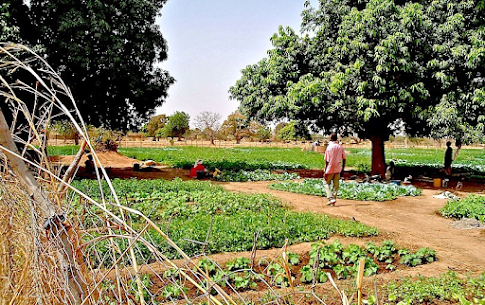
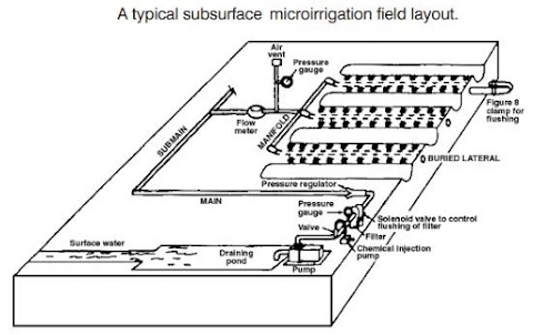
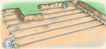
Sub Soil Irrigated Horticulture:
Drip Irrigation (Katra Pashi):
Drip irrigation through pipes and emitters fixed at the end of the pipes is an advanced mechanical technology for water-saving. It provides water to the soil near the roots of the crops promptly and is quantitatively based on the crop's water requirement. A drip irrigation system comprises a Water source, Capital section (Pump, Power, Filter, Fertilizer Injector, Measurement meter), Water-conveying pipes and emitters. Drip-irrigation merely wets the soil near the plant with capillary force without destroying soil structure, thus, Moisture, Air Humidity, Fertilizers, and Heat (No reflected Glare) are always suitable for crop growth. Drip irrigation greatly reduces water loss caused by leaching and evaporation, it is the best one among various technologies in water-saving and is widely used in the irrigation of field and horticulture crops, and shelterbelts. Drip irrigation is applied in afforestation for desert control. Installation of 0.99 mm pipes at the roots of Drought-resistant Plants can raise Water Utilization Efficiency (WUE) 4 times and thus saves money per year. Not only can yields be raised by 30%, water and labor can also be saved by 60% and 40%, respectively, but the input can also be reduced by 3%.
Benefits:
➔ Greater water application uniformity and accuracy, resulting in improved water use efficiency
(WUE) and crop uniformity.
➔ Reduced soil surface wetting, resulting in lower evaporation losses and weed competition.
➔ Greatly reduced periods of anaerobic conditions in the root zone compared to other forms of
irrigation.
➔ Greater ability to manipulate soil water content at peak demand to improve field access,
minimize rotting, etc.
➔ Improved disease control due to improved root zone oxygenation or reduced foliar wetting.
➔ Ability to apply nutrients directly to the center of the active root zone resulting in very efficient
and immediate uptake by the crop.
➔ Minimize nitrate leaching loss potential to groundwater, with good irrigation water
management.
➔ Flexibility in application timing for nutrients and other crop care products.
➔ Little or no application costs compared to any kind of nutrient application made to the soil or
the crop canopy.
➔ The ability to fertigate eliminates the need for application vehicle traffic through the field. there
by eliminating soil compaction, root pruning or other forms of crop damage.
➔ Can easily automate irrigation operations.
➔ Easy Field Access.
➔ Weed Reduction.
➔ Fewer Evaporation Losses.
➔ Reduced Damage from Equipment or Pests.
➔ Reduced Water Temperature.
➔ Reduced Disease Pressure.
➔ Less Lime Scale.
Mung, Haripur, Hazara:
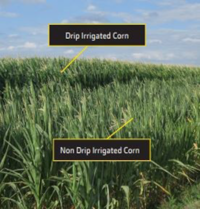
Fertigation is the addition of Water-Based Nutrients to Irrigation water. This saves time, labor, and cost.
PPRC:
Polypropylene Random Copolymer: This the best Drip Piping Material, if painted with Ultra Violet Resistant Paint it is long-lasting and will degrade very slowly in the Sun.
When used under proper pressure and temperature values, the life of PPRC Pipe and Fittings is more than 50 years.
• Its useful life is 50 years under 25 atm pressure (An atmosphere (atm) is a unit of pressure based on the average atmospheric pressure at sea level. The actual atmospheric pressure depends on many conditions, e.g. altitude and temperature) at 20°C.
• It is suitable to use between -20 °C and +95°C. (Insulation must be applied by taking the freezing point of the fluid in the pipe).
• It has high resistance against chemical substances.
• It is corrosion resistant. Also, it is calcification and rust-free.
• They do not change the color, taste, and smell of the water.
• Has smooth and bright internal surfaces.
• No diameter contraction in the welding points. Has high welding performance.
• Provides a saving of 70% in assembly and does not have assembly losses.
• Maintains heat and sound insulation.
• Highly fire-proof (Ref: DIN 19560 and DIN 4102).
• Environment-friendly.
This type of material Drip Irrigation Pipes and Fittings are available in Pakistan from Ms. Griffon Pipes
(PVT)LTD in Lahore.36
36 https://m.me/281673855237
fbclid=IwAR1vva5Ny1d8fGsbhs_KBJq_zmOM5KpShYm7M36FCeSghlxP10AJbctwRJE
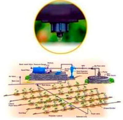

Low-Cost, Shift-able Drip Lines have the advantage of reducing cost inputs by providing the Poor Farmer a single system that he/ she can move to other plots. While labor is increased, the cost is greatly reduced.
A Nepalese Model of Simplified & Low-cost (SLC) Drip Irrigation Technology.
Drip or Trickle irrigation is regarded as a water-saving irrigation technology. There are several advantages of drip irrigation over other commonly used irrigation methods.
Conventional drip irrigation was originally developed in Israel in the early 1950s. It was later widely adopted in other countries like the USA, Australia & Europe, etc. Most countries adopting drip irrigation are the developed ones. The main factors for slow adoption or non-adoption of conventional drip irrigation in developing/ underdeveloped countries are:
➔ Relatively High Capital Investment Cost.
➔ Complex Irrigation Management Process.
International Development Enterprises, an INGO in Nepal has developed a low-cost drip
irrigation technology that is appropriate to micro plots (less than 1 acre). The design was developed &
tested by simplifying the conventional drip irrigation technology with some modifications. The main
modifications are:
➔ Shiftable Drip lines (One drip line for several rows).
➔ Change to a low-pressure system (1 to 2 M).
➔ Simple Filtration System.
➔ Simple & inexpensive fittings.
➔ Easily understandable system.
For the past many years, IDE/ Nepal is implementing the Drip Irrigation Program in some Hill districts of Nepal, targeting poor and marginal farmers. NGOs & Private Entrepreneurs are the main collaborating organizations in the program. Technology is made available to the farmers through local dealers who purchase from Technology Assembler /Distributors. IDE & NGO partners help develop the marketing system of technology. They also provide technical support that includes drip installation/ management & training on agricultural know-how. Drip irrigation has been applied mostly for high-value vegetable crops.
Drip irrigation is made into packages of 3 standard sizes viz. Small, Medium, and Large (to irrigate 125, 250 & 500 Sq. m respectively). Depending on the field size & shape, field lay-out can be done out of the two standard designs Design-A or Design B. The user's price (not subsidized) is about US $ 13 for a Small system. Similarly, it costs $19 & $32 for Medium and Large systems. IDE has trained technicians at the local level to properly install systems & advises users about the technology.
The system broadly consists of the following components. (It will be easily understandable if this is read in conjunction with the attached drawings)
• Head Unit (Tank and Filters).
• Pipe System (Main Pipe, Adjuster, Drip Pipe & Vent Pipe).
• Fittings, & others.
Head Unit: This comprises a 50-L water tank integrated with a filtration system. There are 3 types of filters (Foam, Coarse Screen & Jerry can/ Net) attached to the tank. The tanks also have outlet and overflow arrangements.
Pipe System: Functionally there are three types of pipes used in the system. All of them are made of PVC soft material. Main pipelines (dual lines) connect the Tank outlet to the bifurcation point of the drip pipe. Its diameter is 13 mm.
A small piece of pipe called Adjuster is provided between Main Pipe and Drip Pipe so as to facilitate the shifting of drip lines. The adjuster is further connected with Drip pipe or Lateral, which has accurately punched holes at every 60 cms. The ends of pipes are closed with end plugs. The diameter of both Adjuster and Lateral is 8 mm.
To remove air in the pipe and also to observe the level of water inside the tank, a 60-cm long transparent tube is attached with the Multi connector near the outlet point.
Fittings: The following pipe fittings are used in the system to connect various points.
➔ Nipple /Nut with a pair of Washers: For outlet, and Overflow points in the tank.
➔ Adopter: To connect Jerry can Filter with the Outlet (Inside the Tank)
➔ Multi: To connect Outlet with Main Pipelines. This has 3 branches, 2 for Mainlines, and 1 for Vent Pipe.
➔ Gate Valve: To Run & shut down the water flow in the pipe system. There are two Gate Valves in the system, one for each Mainline.
➔ Tee: To connect Adjuster from Mainline.
➔ Connector: To join the Adjuster and Drip Line.
➔ End Plug: To close the Dead ends of the pipe.
➔ Pegs: To better hold the Drip pipes and ease the pipe shifting process. There are 2 pegs at either end of the drip pipe.
➔ Baffles: As the name indicates, Baffle is the component to break (lie spraying of water out of the drip holes. As such baffles are snapped at each dripping point i.e. 60-cms. spacing. Baffles should not be taken out to prevent breakage. However, they can be moved sidewise to observe and de-clog the drip holes in case they are blocked.
➔ Safety Pin: This item is included in the package so as to clean the drip hole in the events of plugging.
➔ Jute thread: To ensure the correct line during the preparation of crop beds.
➔ Jute Rope: To tie the superstructure for placing the Tank.
Materials & Tools:
The following materials & tools are necessary before installation:
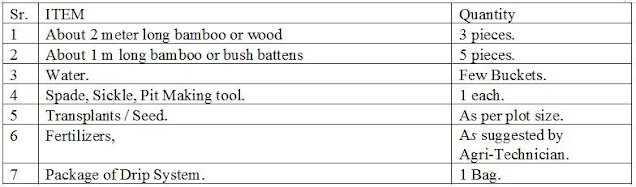
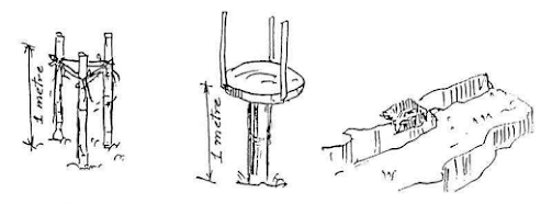
Installation Process:
The following step by step process is suggested to properly install the SLC Drip System.
Chose the right design out of 2 designs depending on your plot size and shape. For larger plots adopt Design-B while for smaller ones Design-A could be more appropriate. Make sure that in no case the length of the lateral exceeds 12 meters.
Having chosen the Design, make the plots as shown in the drawings. A bed width of 90 cm with a 20-cm wide channel in between the beds is recommended for usual vegetable crops.
Decide the position of Head Tank and make the structure for it. Ideally, the tank should be located in the mid-edge of the field as shown in the drawing. The platform of the tank should be approximately 1 meter from the highest point of the crop field.
The tank also can be placed on the ground if it is a rolling or terraced land and the head conditions are appropriate.
Fix the Tank fittings – Outlet Set, Overflow Set, Jerry can Filter & Foam Filter. Keep the Tank on the platform.
Attach Multi Set (Multi with Vent pipe & Gate Valve) at the Outlet Nipple.
Connect Mainline with Gate Valve.
Mark the points of Tee connection. For a coverage rate of "One line for 2 Beds" the place of the tee becomes every alternate channel as shown in the figure. Cut the Mainline Pipe at tee connection points.
Connect Adjuster Set (Tee, Adjuster, Peg & Connector).
Unroll the Drip pipe and cut at the required length (approx. length of crop bed) after measuring different beds.
Insert pegs at ends of laterals. Close the dead ends of pipes with end plugs (Both Main Line and laterals). Keep the laterals almost straight along the proposed plant row.
Fill the tank with water. It is good to clean the tank before placing it onto its platform. Open the Gate Valve and let the water drip for a few minutes. Close the Gate valve. Shift the lateral into the next proposed row and again let the water drip by opening the Gate valve.
Mark the spot of wet places by digging small pits.
Dig the pit of the required size and mix fertilizers. Allow sufficient time before planting after mixing fertilizers.
When it is ready for transplanting or seeding, run the system again and finalize exact planting spots. Put your plants /seeds at the dripping points.
Management Guidelines of SLC Drip System:
Basic Preparation: Make sure that:
➔ You have water to put into the tank.
➔ Dripping points are at correct places i.e. close to the plants.
➔ The ends of the pipe are not open.
➔ The filter is clean & there is no debris left.
➔ All joints are in good working order (absence of faulty & disconnected joints).
Irrigation:
1. Keeping the Gate Valve closed, fill the tank up to ¾ inch height.
2. Open the Gate Valve & irrigate. After a while, water should drip from each dripper. Clean the dripper by jarring with fingers. If necessary, insert & pull safely pin into the hole. If several holes are found clogged at the same time the pipes should be flushed by opening the end plugs.
3. Irrigation duration & frequency: This depends on a large number of factors. However, as a rough guide the following recommendations are made:
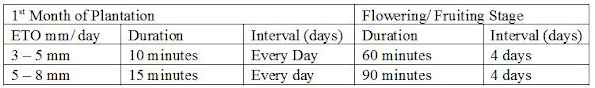
Note:
➔ Irrigation should be more frequent in sandy soils.
➔ If it rains the interval & duration of irrigation should be fixed based on soil moisture status.
Regular Maintenance works:
➔ Filter cleaning (All filters) looking at the filter condition.
➔ Cleaning plugged holes.
Storage:
At the end of the crop season, the system components should be cleaned. In the rainy season, it should be stored properly and reinstalled at irrigation time.
Some Important points:
➔ The drip system, whether in the house or field, should be protected from animals & curious children. It is thus good to have some fence around the drip plot.
➔ Never keep the open ends of pipes in contact with soil/ dirt.
➔ The drip hole should be just below the interior channel of the baffle.
➔ Every care should be taken while shifting the drip pipes.

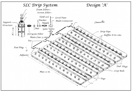
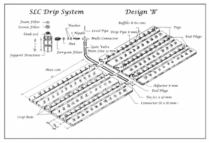
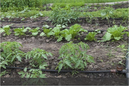
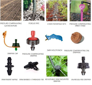
Irrigation Through Low-Pressure Pipes:37
A new water-saving technology to irrigate fields with low-pressure water through pipes instead of channels. The pipes are of PVC with a diameter of 110-160 mm and a thickness of 1.8-3.3 mm. The pipes should be made complying with the following 5 indexes:
1. Pull resistance δ ≥42MPa.
2. Flat rigidity PS = (0.92-0.64)× 105kPa.
3. Shock resistance of low temperature, over 20N.m.
4. Explosive resistance of momentary inside pressure (20-14)× 105KPa.
5. Elasticity modules E = (3.1-3.9)× 103MPa.
2 Water-saving Irrigation Technologies in Arid Areas Xu Xianying Wang Jihe E Youhao Zhu Shujuan (Gansu Desert Control Research Institute, Wuwei 733000)
After being selected, the pipes are installed according to the irrigation design. Pipes are generally buried under the ground and above frozen earth. The furrows should be straight and can not be deviated ± 30 from the central line, the furrow bottom is arc-shaped. Pipes are connected through the thermoplastic stress method and the temperature should not be over ± 3, the length of lap joint is 1.2 - 1.5 times pipe diameter.
Irrigation through low-pressure pipes can save energy and reduce evaporation and leakage, and is convenient for management; PVC pipes are easy to transport as they are light, corrosion-resistant and need little investment.
Irrigation Through Permeable Pipes:
With this kind of irrigation, water can seep into the soil through special permeable pipes and provides moisture directly to the plant roots according to the movement dynamics of water in the branch pipes. Pipes for permeable irrigation are usually made from PVC pipe, brick, and clay products.
As far as clay product concerned, it has good permeability, is corrosion-resistant, and needs little investment.
The pipes are generally buried under the ground, depth depends on the soil characteristics and plant species, etc., generally, it is 40-60 cm. When installing, pipes should be straight and flat and the lap joint should be fixed. Permeable irrigation is efficient in reducing evaporation loss and leakage.
Compared with traditional flood and ditch irrigation, it can save water by 80%, 60%, respectively.
Strip Irrigation:
This is one of the field irrigation methods applied in arid areas. The technical requirements of this type of irrigation are fine preparation of the land, reasonable design of irrigation area, and control of flow and time of irrigation water. Irrigation area generally is (30-100) × (2-4)m2, water flow entering into the unit area should be controlled within the range of 3-6 L/s/m, and the slope of each plot should be 0.001 – 0.003 m.
Irrigation on Plastic Film Strip:
This technology provides flowing water on plastic film and water crops through holes in the sheet (used for the ventilation of seedlings). This method makes irrigation uniform. Irrigation in the film is an advanced water-saving technology and is suitable for arid areas. It needs little investment, can raise yields, is easy to operate and to control the water flow, can speed water flow, and reduce water loss from leakage and infiltration. The technical points of this kind of irrigation are soil types, field slopes, irrigation intensity, water flow and its speed, irrigation area, irrigation quota and irrigation time, etc.. Irrigation intensity is relevant to water flow and soil characteristics and can be calculated with the formula: q = 0.001 knvw
where q = irrigation intensity L/ (N.m),
k = coefficient of side infiltration, it has a direct proportion to the water on the film and adverse proportion to the length of the plot. For those without side infiltration belt, k = 1.48 – 1.86, the average is 2.66;
n - holes on the film of each meter, including the holes for the seedling ventilation and holes special for irrigation;
v - infiltration speed of soil. It reduces with the increase of irrigation time and can be defined through
field measurement, cm/h;
w - the average area of irrigation holes, m2.
This technology has been extended at a large scale in arid areas of China. Compared with traditional irrigation, it can save 40 - 60% water and can raise yields by 25%.
The main forms of filmstrip irrigation are as follows:
A. Strip irrigation on the plastic film
Plant crops in a strip and cover with plastic film.
When irrigation water flows on the strip, water infiltrates into the soil through holes.
B. Furrow irrigation on the plastic film
Prepare the land as intervals of ditch and ridge, put film at the bottom and back of ditch, plant crops there. This pattern is especially suitable for melons and vegetable plantation. Ditch size depends on different crops, e.g., for the seed-melon plantation, the ditch is 30cm deep, 40cm wide for the upper mouth and the interval of furrows is 90cm.
Misting/ Fogging Irrigation (Dhund Pashi):
The use of Fogging Equipment can provide countless benefits in many agricultural applications:
➔ Mushroom production.
➔ Orchid growing.
➔ Vegetable and fruit storage.
➔ Livestock cooling and dust control.
➔ Greenhouse chemical fogging.
➔ Greenhouse cooling and humidification.
➔ Greenhouse propagation.
➔ Bare root storage.
➔ Tobacco conditioning.
Misting Irrigation:
A very fine mist is emitted from overhead sprinklers, distributing needed moisture ideal for plant propagation and seed germination. Misting systems carry the benefit of fending off plant diseases, minimizing plant stress and increasing growth rates. They also help establish the ideal greenhouse environment, keeping it cool, moist, humid and consistent at all times. Misting irrigation systems have a number of suitable small- to large-scale applications.
Overhead Spinner Sprinklers: Mainly used for crops that tolerate wet foliage, overhead sprinklers employ pipes placed above the plants and fitted with nozzles that can be adjusted to varying spray ranges. These often use automatic controls, which offer a time savings to the gardener who can tend to other tasks, but the system should be checked often to ensure it is working properly. Overhead sprinkler systems work well for watering small transplanted plants until they are ready to be placed in a garden or flower bed.
Mist and Fog Equipment for Propagation:38
What is the difference between fog and mist?
Fog particles are generally considered to be less than 50 microns (0.002in) in diameter. The particle size typically used in high pressure greenhouse fog systems is about 10 microns. Mist, on the other hand, is particles from 50 to 100 microns. As a comparison, human hair is about 0.004in diameter that equals 100 microns. Breaking one gallon of water into 50 micron droplets will produce about 68 billion droplets of fog.
Injected into the air, tiny water droplets of fog remain suspended until they are evaporated. The smallest particles vaporize almost instantaneously. The larger ones are carried by air currents, gradually becoming smaller until they are vaporized. Mist size particles are heavier and take much longer to evaporate. These are more likely to fall out and wet the plant surface or saturate the growing medium.
If they don't evaporate before nighttime, the potential for disease increases.
38 https://ag.umass.edu/greenhouse-floriculture/fact-sheets/mist-fog-equipment-for-propagation
How Fog and Mist work for Propagation:
The humidity in the air affects the evapotranspiration rate from the leaf surfaces. To get good propagation, a balance between humidity and transpiration is needed to allow water and nutrient uptake
without excess dehydration. In a crop with a dense foliage canopy and without much air movement, a boundary layer of moisture approaching saturation develops around the plants. If the growing medium is also saturated, there is a potential for problems from fungi, moss, gray mold and fungus gnats.
On the other hand, when the air temperature is high and leaf temperature increases, water loss can exceed the ability of the plant to up take moisture and stress can build up within the plant. The use of fog and mist at this time can reduce the air temperature and increase the humidity within the plant canopy without saturating the plant medium. With more oxygen in the root zone, faster rooting occurs. Once the root system is established, the relative humidity can be reduced.
Experience is usually the best approach to determining the proper humidity level. The following can be used as a guideline:
Establishment phase 60 - 80% relative humidity
Rapid growth phase 55 - 70% relative humidity
Hardening phase 45 - 50% relative humidity
Another advantage of the fog system is that foliar feeding, insecticides and fungicides can be applied automatically with a fog system. This saves time and gives a uniform application.
Fog Systems:
Several methods are used to produce fog. A typical system uses a high pressure pump, distribution piping and nozzles that break the water stream into very fine droplets. Piston pumps are needed to develop the 800 to 1200 psi pressure to get the 10 to 20-micron size droplets. Most systems available from irrigation equipment suppliers and labeled as fog systems operate on 50 to 60 psi irrigation water and create a droplet size larger than 50 microns. They are really mist systems.
Copper, stainless steel, and re-enforced flexible hose are used for piping. Diameter is frequently 1/4in or 3/8in as water supply required is only 1 to 2 gallons/hour/nozzle. For propagation, lines of pipe are evenly spaced above the crop area.
Plastic, ceramic and stainless steel are used for nozzles. Nozzles should have anti-drip check valves to prevent dripping after the system shuts off. An integral strainer will keep the nozzle from clogging.
The greatest problem associated with fogging systems is nozzle clogging from chemical and particulate matter. Calcium deposits can coat the inside of the pipe and nozzles reducing flow. Water treatment or the use of rain water or bottled water can solve this problem. Several levels of filtration of particulate matter should be installed.
Fog can also be produced by a system using a high-speed fan with water channeled to the tip of the blades. The shearing action as the water exits the blades produces a fine fog. The fan distributes the fog above the crop canopy. This system has the advantage of less clogging as nozzles are not used but some growers have had to remove the system because of the high noise level.
Water at household pressure, injected through a nozzle into a stream of compressed air will also produce a fine fog. Each nozzle requires both a water and air supply. Different flow rates and droplet sizes can be achieved by adjusting the water and air pressure. Distribution can be through ducts, HAF fans or nozzles evenly space over the crop.
For small areas, some growers have used an electrothermal aspirator with good results. Fog systems frequently operate with a controller or computer that measures vapor pressure deficit (VPD). The difference between saturation water vapor pressure and ambient water vapor pressure is the VPD and represents the evapotranspirational demand of the surrounding atmosphere as well as the proximity to the dew point. Due to the fact that relative humidity varies with temperature, it is better to manage propagation with VPD. By maintaining the VPD below one, water stress within the plant can be kept at an acceptable level.
Mist Systems:
A mist system contains piping, nozzles, filter, pressure regulator, solenoid valve, and timer or controller. Several types of nozzles are available that develop mist size droplets. These include the deflector or impingement type which operates at 30 - 60 psi water pressure. A leak prevention device (LPD) is frequently added to eliminate dripping. A 100 - 150 mesh strainer in the line will prevent the fine holes from clogging.
Installation should follow the system manufacturer's recommendations. Nozzles can be supported above the bench on risers or suspended from a cable overhead. Most misting nozzles should be placed 3ft to 5ft above the crop. Spacing is usually on a grid of 3ft to 5ft. Overlap of 100%, or more, is necessary to get uniform coverage of the crop.
A solenoid valve is needed to turn the water on and off. The valve should be the type that normally closes with a snap action operation and it should have the same voltage as the time clock or controller. A 24-volt system is safer than a 220 – 240 volt one.
Mist systems can be controlled with a time clock and timer, mechanical sensor, light-operated interval switch (LOIS), humidistat or controller. The time clock governs the time of day the system operates. The timer turns the mist on for several seconds every few minutes (Example: 3 seconds every 3 minutes). The mechanical sensor is usually a screen placed in the plant canopy that collects moisture and turns off a solenoid valve when it gets heavy. The LOIS sensor is mounted next to the glazing and counts the amount of light it receives. On cloudy days it counts slower than on sunny days and triggers the solenoid more frequently. The humidistat is a switch that senses the humidity level of the air and activates the solenoid when the level falls to a preset point. Controllers are made to handle multiple zones and usually operate based on time.
A Greenhouse Misting System is important to help grow healthy and vibrant plants in your greenhouse. There are many benefits to having a misting system in your greenhouse.39
Maintenance:
A greenhouse misting system helps with greenhouse maintenance. Because greenhouse misting systems produce favorable and consistent conditions throughout the year, they are helpful for fending off plant diseases, minimizing plant stress, and increasing germination and growth rates.
Humidity:
Anyone who has some experience with growing plants in a greenhouse knows how important it is to maintain consistent humidity levels. Often gardeners have to deal with low humidity and high temperatures. If the humidity is not controlled properly, plants can become damaged and even die. If the humidity drops below 30%, the plants can stop growing. A greenhouse misting system produces a high-pressure fog or mist that evaporates instantly to cool and humidify, without causing too much moisture to accumulate.
Temperature:
Another advantage of a greenhouse misting system is that it reduces temperatures in a greenhouse by up to 30°F, in addition to keeping the humidity levels consistent. Because plant leaves absorb substances from the air and give off moisture, the best environment to encourage healthy growing plants is created with a misting system.
Fertilizer:
Another benefit of a greenhouse misting system is that it can be used to apply fertilizers to the greenhouse more easily. The mist lands on the leaves of the plants, making the fertilizer easier to be absorbed. Misting systems for greenhouses make delivering fertilizer efficient and consistent.
39 https://www.doityourself.com/stry/3-benefits-of-a-greenhouse-misting-system
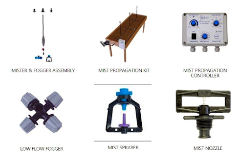
Innovative Cultural Practices:
Reusable plastic trays to collect dew from the air, reducing the water needed by crops or trees by up to 50 percent. The square serrated trays, made from non-PETrecycled and recyclable plastic with UV filters and a limestone additive, surround each plant or tree.With overnight temperature change, dew forms on both surfaces of the tray, which funnels the dew andCondensation straight to the roots. If it rains, the trays heighten the effect of each millimeter of water27 times over.
The trays also act as mulching and block the sun so weeds can’t take root, and protect the plants from extreme temperature shifts. “Farmers need to use much less water, and in turn much less fertilizer on the crop,” which translates to less groundwater contamination.
Spray Irrigation Technology (Fawara Pashi):
This method provides water to the field through the pressure pump or water droplets, and then sprays water evenly through the spray head. It is mainly used in big farms in arid areas and in those places where land is plain, water permeability of soil is good and where it is difficult for flood irrigation. There are three types of spray irrigation: fixed, semi-fixed and mobile Compared with flood irrigation, spray irrigation can save water by 30-50% and raise yields by 10-30%.
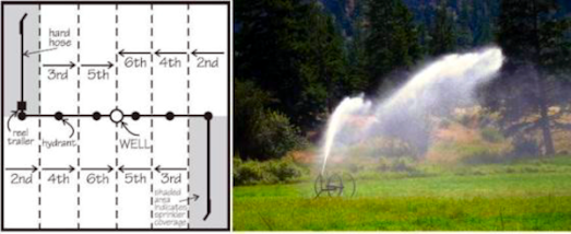
Trailer Mounted Rain Gun.
Fixed Rain Sprinklers.
Radial Sweep Sprinkler:
Rain Gun Head
Fixed Rain Gun.
Traveling Trolley Mounted Rain Gun with Diesel Engine. Mung, Haripur, Hazara.
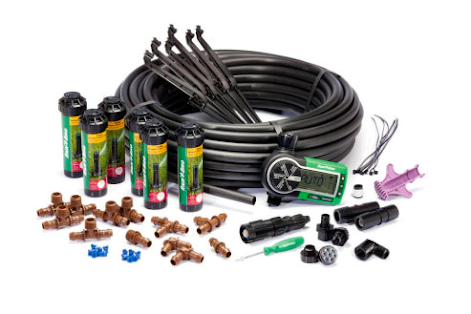
This all-in-one kit includes everything needed to install a complete underground sprinkler system capable of watering an area from 1,000 to 3,000 square feet; conveniently sourcing water from any outdoor hose faucet. An easy-to-install, affordable and effective automatic sprinkler system for Small Plots. Kit provides all the supplies necessary for a simple five-step installation. Kit consists of: 125 feet of 1/2" distribution tubing, fittings, six professional grade high-efficiency pop-up rotary sprinklers and a durable, professional-grade automatic hose-end timer. The dependable Rotors feature Rain Bird's patented Rain Curtain™ nozzle technology which delivers a rotating curtain of large water droplets that fall exactly where you want them and resist windblown overspray. Water disperses evenly from nozzle to end of stream to reduce watering time and save money. "Micro Ramps" on nozzle direct a portion of the spray close to the head eliminating dry brown spots. Provides a true 4" pop-up height to clear taller grass. Simple adjustments for spray rotation and distance help keep water on your plot and off walkways. Water-lubricated, gear-driven design provides long-lasting dependability. A dual-action, positive-stop wiper seal protects the internals from debris while assuring positive pop-up and retraction. Adjusts easily from 40° to 360° part-circle arc, and reversing full-circle arc rotation using a flat head screwdriver. The robust hose-end timer features a large display and simple programming allowing users
to enter a desired watering schedule for any days of the week they choose up to two times a day. The sophisticated, yet simple timer is easily customizable to comply with specific needs, such as watering sloped areas and avoiding runoff. "Water Now" and "Cancel Watering" settings provide optimal control without interrupting pre-programmed settings. “Cancel Watering” feature also operates as a "Rain Delay" allowing selection of up to a 96-hour pause in watering before stored programming resumes.
Recommended water pressure: 40 – 75 psi.40
Installing an underground sprinkler system.
40https://www.amazon.com/Rain-Bird-32ETI-Automatic-Sprinkler/dp/B00K72WU3Q?SubscriptionId=AKIAILSHYYTFIVPWUY6Q&tag=duckduckgo-d 20&linkCode=xm2&camp=2025&creative=165953&creativeASIN=B00K72WU3Q
Outline your plot and other structures.
Show walkways and other surfaces.
Identify trees and major obstacles.
Measure and record the perimeter of your plot.
Identify slopes.
Show groundcover.
Identify the size and location of the water main line.
Identify the soil type in your yard.
There is a simple way to determine what type of soil - sand, loam or clay - you have in your yard. All it takes is a clean, empty jar with a lid, some clean water, a tablespoon of detergent and a sample of the soil you want to test.
1. Fill the jar about 1/3 full with the soil to be tested.
2. Fill the jar with water and detergent then cap it.
3. Shake the jar vigorously and set aside for several hours or overnight.
EVALUATE THE RESULTS:
SAND If the water is clear and the soil has settled to the bottom; you have predominantly sand soil.
LOAM If the water is still a little murky with bits of matter suspended in it; you have loam soil.
CLAY If the water is still murky and there is a visible ring of sediment around thejar; then your soil is mostly clay.
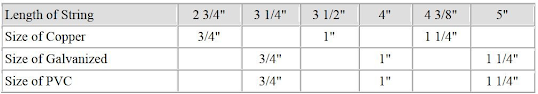
Choose "small to medium" area sprinklers for areas smaller than 25 by 25 feet.
Choose "medium to large" area sprinklers for areas larger than 25 by 25 feet.
Rotors or Sprays?
The size of the area which needs to be irrigated is the main factor that will determine whether to use a rotor or a spray in any area in your irrigation layout. Rotors can cover a much greater area which makes them suitable for areas that are expansive. Some of the benefits of using rotors are that they can be spaced out farther apart which requires less heads to get the job done and less trenching. The maximum throw for a rotor is around 70 feet and the minimum throw of approximately 20 feet. In comparison sprays throw water a much smaller distance (4 to 17 feet)+ so they are suitable for smaller areas.
Pipe Layout:
Supplies:
➔ Controller.
➔ Rain or rain/freeze sensor.
➔ Backflow protection.
➔ Ball valve (isolation valve).
➔ Supply line tie-in (kwikfix, PVC fitting).
➔ Valve boxes.
➔ Insulation for above ground PVB and wall weather tape.
➔ Pipe: schedule 40, class 200, 1”, ¾”.
➔ Teflon tape.
➔ PVC primer and cement.
➔ Valves.
➔ Wire: 16 gauge direct burial. One white for common. Balance red.
➔ Waterproof wire connectors.
➔ Swing joints or cut off risers.
➔ Sprinklers bodies.
➔ Spray nozzles.
➔ Rotors.
➔ Shrub sticks/risers.
➔ Shrub adapters.
➔ Misc fitting: connectors, T’s, reducers, elbows, 45s, threaded for PVB.
Liquid Fertilizer Injector:
A well designed irrigation system puts water where the plants need it and adds fertilizer while it runs. In-line fertilization will help your plants grow and save time and effort. The Fertilizer Injection System ties directly into the sprinkler system, runs automatically with no extra wiring, and lets you control the amount of fertilizer applied. Fertilizer used is liquid based as opposed to granular fertilizers. The system allows for fine tuning the amount applied with a simple twist of a dial. And, because the fertilizer is completely dissolved in the water, it will not harm or cause any performance drop in the sprinklers.
The Injector is installed out of site, usually underground, and attaches to the sprinkler system with 2 small hoses. After connection the tank is filled and the application rate is set.
Caution: before installing any system that ties into the irrigation system you must have a backflow preventer.
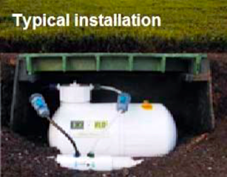
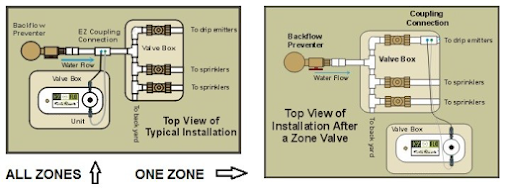
Liquid Fertilizers:
Liquid formulations, when applied to the Foliage of Plants, have an absorbtion rate of 70% as comppared to 30% absorbtion rate of Granular Fertilizer applied to the soil. Thus Fertilizer Efficience is increased, resulting is savings of cash input. With its rich source of humates, pure mono and di-valent minerals as Primary, Secondary and Micronutrients as well as Natural enzymes and Growth Regulating Hormones, complete formulation products stimulate the growth of microbes and bacteria which in turn provide food sources targeted to the all plants. The Formulation is Non-Toxic, Non-Pathogenic and Environmentally Safe. It is a Water based or soluble powder for root and foliar feeding. And ensures availability of essential nutrients as an off the shelf source for Plant uptake whenever required in different Growth Stages.
Sprinkler Heads:
Spray Heads – These sprinkler heads dispense high volumes of water in short periods of time. They are best suited for flat, even areas; do not use them on slopes. They are also suitable for small, hard-to-reach areas.
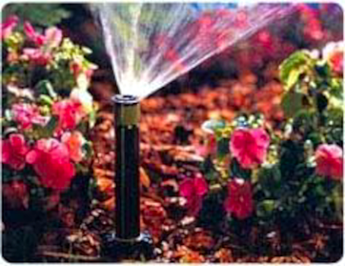
Rotor Heads – When you need to water large expanses, rotor heads are the best option. They have a
much lower application rate than spray heads. Rotors are used to save labor on installation since they
cover a larger area than spray heads so they can be spaced much further apart. They are also a better
choice for sloped areas or for areas that are made up of clay soils since they apply water at a slower rate
than spray heads and thus help prevent water run off.
Master Valve:
A master valve is an electric valve installed at the supply point which controls water flow into
the main piping system. When this valve is closed water will not be supplied to the irrigation system. A
master valve will greatly reduce any water loss due to a leaky station valve because the leaky station
valve can only leak while the master valve is providing pressure to the system. Also, if you damage the
irrigation main line, a master valve will control water loss so the main can be repaired without shutting
off the water supply. A master electric valve is typically the same type of valve as used for station
valves, but rather than being installed downstream from the main line and connected to a station output
in the controller it is installed upstream at the front of the main line and connected to the “master” or
“pump” connection in the controller.
Irrigation Controller.
Irrigation controllers, also known as irrigation timers or sprinkler system timers, are the nerve centers or brains of the sprinkler system. Sprinkler system timers send electric signals to the irrigation valves. The valves regulate the flow of water to the sprinkler system. Irrigation Sprinkler System timers are the devices that set a watering schedule to meet needs. You can set the days you want to water, the time of day you want the sprinklers to come on, and how long you want them to apply water. Sprinkler system controllers may be mechanical, partly automatic, or fully automatic. Irrigation sprinkler system timers are largely maintenance-free. Sprinkler timer installation or replacement is very straightforward and easy and can be done by either the owner or by an irrigation professional.
How to Choose an Irrigation Controller / Timer:
The only important decisions needed to make when selecting a controller / timer are as follows:
1. Controller mounting location: indoor or outdoor.
2. Number of stations or zones – must be at least as many zones or areas the sprinkler system is broken up into.
3. Number of programs (1, 2, 3, or 4) – should have at least 2 or more programs to provide the watering flexibility needed.
Features Available on a Controller
Some controllers come fully loaded with features for efficiency and convenience of operation. In others, extra features may be optional. Key features available on a controller can include:
➔ Clock and Calendar Settings:
The user can program watering times, control watering cycles, and make seasonal adjustments.
➔ Manual start and Manual Station Operation:
The user can operate the stations or start the automatic cycle without affecting the programmed start time. This is helpful when you need to do some maintenance to your system. This feature makes it easier to check for leaks, misaligned or broken sprinkler heads and even perform basic tune-ups steps such as adjust spray patters and replace nozzles.
➔ Master Switch:
The master switch overrides the automatic functions of the stations.
➔ Master Valve Control:
The master valve prevents flow to the system, in case of water problems or system failure.
➔ Station Omission:
The user chooses which stations operate, and which do not.
➔ Pump Start Lead
This turns on a pump start relay whenever a station activates, to combine irrigation and pump control. A Pump Start Relay is an electronic device that uses a signal current from the irrigation controller to activate a pump to provide water to the irrigation system. Never connect the controller directly to a pump as damage to the controller will result.
➔ Rain Sensor:
A rain sensor shuts down the irrigation system if it detects rain. The purpose of a rain sensor is to stop watering when precipitation is sufficient. Most controllers allow for a sensor to be connected directly to the controller and allow you to easily override the sensor by using a Rain Sensor Bypass switch on the controller.
➔ Battery Backup:
➔ The controller reverts to battery power in case of power interruption or outage. The battery typically will just allow the timer to maintain the time, date, and watering schedule. On some controllers it allows the user to program the controller without AC power.
IMPORTANT:
Watering will not occur without AC power. The battery only keeps the time, date, and watering schedule in memory until the AC power is restored or the battery dies.
➔ Non-Volatile Memory:
The controller retains its program data without a battery, even if the power fails. The nonvolatile memory allows the timer to maintain the time, date, and watering schedule indefinitely.
➔ Delay:
The delay feature allows time for valves to close fully in one zone, before opening the valves in another zone.
Figuring out how to measure a slope or calculating how many zones of Irrigation needed.
Determine the Percentage of Slope
➔ Divide the measure of height by the measure of length and multiply by 100. Don’t worry about exact inches. Round to nearest quarter foot. For example, 12’ 1” = 12’, 13’7” = 13’6” or 13.5 feet.
Example above: 2 divided by 14 times 100 = 14.3%
Pumping Water Low/ No Energy:
1 HP/ Alternate Energy, Jack Pump for 6-8” Water Delivery:
The energy crunch and high cost of living needs an adequate response on urgent basis. One such
intervention is to reduce the cost of pumping water and also provide a means of using alternate energy
effectively.
The tremendous savings that can be affected in Agriculture, as well as Public Health Water Supply, if a low cost Pumping system is provided, will make both Disciplines more Cost Effective.
Pumpjack Components:
1. Base
2. Samson Post
3. Center Bearing
4. Clamp Block
5. Carrier Bar
6. Wireline Assembly
7. Horsehead
8. Walking Beam
9. Counterbalance Adjustment Screw Assembly
10. Beam Weights
11. Brakeshoe w/Lever Assembly
12. Saddle Bearing Lube Line
13. Tail Bearing
14. Pitman
15. Tail Bearing Lube Line
16. Crank Pin Bearing Assembly
17. Crank Arm
18. Gear Reducer
19. Sheave
20. Motor Rails
21. Brake Lever
Water Well Pumpjacks.
Pumpjacks can also be used to water wells. The scale of the technology is smaller than for an oil well, and can typically fit on top of an well head. The technology is simple, typically using a parallel-bar double-cam lift driven from a very low horsepower electric motor. The flow rate for a water well Pumpjack is low compared to a jet pump and the lifted water is not pressurized.
The Hydraulic Ram:
The search for a "perpetual motion" machine is just about as old as civilization itself. And though we all know that such a gadget probably doesn't exist, there is a piece of equipment that comes pretty close: the hydraulic ram pump. The water ram (also known as a trompe) has been around for quite a while and was a widely used means of pumping water before electricity became common in rural areas. Strictly speaking, the ram pump doesn't create its own power but draws energy from the force of a moving column of water, usually fed through a pipe from a point more than 18 inches above the trompe. Although the hydro ram won't operate without a fluid power source, it will work indefinitely when water is present. And, except for an adjustment every few months, the device requires no maintenance whatsoever!
Water enters the ram from the thick drive pipe and runs out of the impulse valve, which is held open by a spring (or weight in larger pumps). As the momentum increases, the pressure of the water will drag the impulse valve shut. This creates a shock wave inside the ram body, pushing water past the delivery valve (a non-return valve). As the pressure subsides the impulse valve opens and the cycle begins again. This takes place more than 100 times a minute, depending on the head pressure and tuning of the impulse valve, and each pulse pushes up a small quantity of water through the thinner delivery pipe. The air chamber cushions the flow. The tiny snifter valve below the chamber allows a small quantity of air into the air chamber with every pulse to replace air lost into the deliver pipe. A small squirt of water will come out on the recoil.
https://www.motherearthnews.com/diy/hydraulic-ram-pump-zmaz79mjzraw
Importance of Fresh Water.
Water resources are essential for satisfying human needs, protecting health, and ensuring food production, energy and the restoration of ecosystems, as well as for social and economic development and for sustainable development.
Freshwater problems centre on two issues: quantity and quality. Issues of quantity involve both shortage and excess, both of which affect and are affected by environmental management.
Issues of quality concern the pollution of water bodies to the degree that the use of such bodies is restricted.
Freshwater is a fundamental requirement for human survival and socio-economic development. Chapter 18 of Agenda 21 highlights the importance of water and indicates the way to a secure, sustainable water future.
Sources of River Pollution.
There are several sources of water pollution which work together to reduce overall river water quality. Industry and agriculture discharge liquid waste products. Rain as it falls through the air, or drains from urban areas and farmland, absorbs contaminants. Serious incidents resulting from spillages or discharges of toxic chemicals are the pollution events that make the news. The impact of a slow build-up of pollution over a long time and in a wide area can be even more serious.
Acid Rain.
Rain falling through polluted air absorbs some of the pollutants as it falls. The main pollutant gases are sulphur dioxide and nitrogen oxides, which form when fuels are burned.
They react with rainwater to form sulphuric and nitric acids. On reaching the ground the acid liquid has many effects. It can release harmful substances such as aluminium and heavy metals from the soil. These are normally present in an inert, harmless state, but in acid conditions can turn into compounds poisonous to plant and animal life. When washed into lakes and streams the aluminium can kill small water creatures and fish.
Industrial Pollution.
Many industrial wastes discharged into water are mixtures of chemicals which are difficult to treat. Some industrial wastes are so toxic that they are strictly controlled, making them an expensive problem to deal with.
Agricultural Pollution.
When organic farm wastes like silage or liquid manure (slurry) escape into rivers, the amount of oxygen in the water is reduced. Nitrate pollution problems occur when too much chemical fertiliser is applied to the land. The excess runs off and can find its way into drinking water sources, or can trickle into rivers and lakes. Some experts believe that high levels of nitrate in drinking water may pose a threat to health.
In rivers, streams, ponds and lakes, too much nitrate can create great problem, the water becomes clogged with fast-growing plant life like algae and weeds.
Other Sources of Water Pollution.
• Abandoned mines produce a large quantity of polluting chemicals. Many dangerous metals including iron, aluminium, tin, lead, mercury and cadmium come out of old mine workings.
• Phosphorus from sewage is another powerful pollutant. It comes from detergents and stays in rivers for a long time, taking up valuable oxygen. fish, small water creatures and plants.
Cleaning Technology.
Cleaning the river has two strategies.
1. Physically clean up of the river.
2. Control the pollution at the source.
Multilateral Environmental Agreements (International).
Some of the multilateral agreements are listed below:
• Convention on the Law of the Non-Navigational Uses of International Watercourses
• Protocol on Water and Health to the 1992 Convention on the Protection and Use of Transboundary Watercourses and International Lakes
• Convention on the Protection and Use of Transboundary Watercourses and International Lakes.41
41http://www.eisil.org/action.php?sid=664218518&url=http://www.unece.org/env/water/text/text.htm&action=go&id=473
Regional Agreements
At least ten conventions are included within the Regional Seas Program of UNEP, including
1. Abidjan Convention, 1984 ( Atlantic Coast of West and Central Africa).
2. Antigua Convention (North-East Pacific).
3. Barcelona Convention Mediterranean.
4. Cartagena Convention (wider Caribbean).
5. Lima Convention, 1986 (South-East Pacific).
6. Noumea Convention (South Pacific).
7. Nairobi Convention, 1985 (East African seaboard).
8. Kuwait Convention (Kuwait region).
9. Jeddah Convention (Red Sea and the Gulf of Aden).
10. Addressing regional freshwater issues is the 1992 Helsinki Convention on the Protection and Use of Transboundary Watercourses and International Lakes (UNECE/Helsinki Water Convention).
Legislation Related to Water in Pakistan.
Federal Water Laws.
Freshwater
• Canal and Drainage Act 1873.
• Indus River System Authority Ordinance 1992.
Marine and Coastal Water
• Territorial Water and Maritime Zones Act 1976.
Energy/Hydel Power
• Electricity Act 1910.
• Electricity Control Ordinance 1965.
• Regulation of Generation, Transmission and Distribution of Electric Power Act 1997.
• Natural Gas Regulatory Authority Ordinance 1997.
Sindh Water Laws
Freshwater
• West Pakistan Water and Power Development Authority Act 1958.
• West Pakistan Water and Power Development Authority (Amendment) Ordinance1964.
• West Pakistan Water and Power Development Authority (Amendment) Act 1967.
• West Pakistan Land and Water and Power Development Board (Reclamation Fee)Rules 1965.
• West Pakistan Land and Water and Power Development Board (Authority forPayment from Board Fund) Rules 1966.
• Karachi Water Management Board Ordinance 1981.
• Sindh Canal and Drainage Act 1991 (may be no such law).
• Canal and Drainage (Extension to Rohri Canal Area) Act 1991.
• Karachi Water and Sewerage Board Act 1996.
Marine and Coastal Water
• Coastal Development Authority Act 1994.
Agriculture.
• Sindh Irrigation Act 1879.
• Sindh Irrigation (Amendment) Act 1976.
• Sindh Irrigation (Amendment) Ordinance 1984.
• Sindh Irrigation (Amendment) Ordinance 1999.
• Sindh Canal Water Flat Rate Rules 1972.
• Sindh Irrigation Water users Association Ordinance1982.
• Sindh Irrigation Water users Association (Amendment) Ordinance1984.
Energy/Hydel Power.
• West Pakistan Water and Power Development Authority Act 1958.
• West Pakistan Water and Power Development Authority (Amendment) Act 1967.
Environmental Legislation.
The National Water Policy has been adopted. This is a landmark manifestation and commitment of national cohesion and unity and owing to comparatively lesser priority given to water sector projects for decades in view of their long gestation periods staggering beyond the 5-year tenure of any elected government with continuously dwindling financial allocations from as high as 13% of PSDP in FY 2009-10 to minuscule 3.7% in FY 2017-18. This Charter is therefore a “CALL FOR ACTION” and “THE DECLARATION of A WATER EMERGENCY”. It proclaims as “We must now look beyond our differences and come together as a nation to rise to the challenge that is before us. We have done so before, and we can do it again. We will seize the day and secure our collective future. This is our promise to the coming generations”. 42
42 National Water Policy & Water Charter 2018 (24-04-2018)
http://mowr.gov.pk/wp-content/uploads/2018/06/National-Water-policy-2018-2.pdf
Conclusion:
"Pakistan has one of the largest irrigation systems in the world. More than 90% of its water resources are used in agriculture. However, more than 60% of the water used in agriculture is lost during the conveyance and application in the fields. The losses in the field are mainly due to conventional irrigation practices such as flood basins and over irrigation. Over irrigation is mainly due to lack of knowledge about irrigation scheduling and misconception of the farmers that more water will produce more yield.
Growing of rice in standing water is a classical example of this mindset due to which rice has become one of the largest user of freshwater resources. This leads to very low water productivity of rice as compared to other grain crops. With declining freshwater availability, the production of rice with the existing practices is becoming highly uneconomical and unsustainable. In fact like other crops, rice has a specific water requirement for a particular agro-climatic region. However, with the existing practices, it is not possible to apply water to rice crop according to its requirements. Various options are now being evaluated to save water in rice fields such as bed and furrow, direct seedling, reducing ponded depth to soil saturation or by alternate wetting/drying.
According to the Pakistan Council of Research in Water Resources (PCRWR) conducted a series of experiments in the field to evaluate the prospects . This practice of growing rice on beds not only saves water but has several other advantages over the conventional flood irrigation (submerged) such as better fertilizer-use efficiency, better yield, ease in transplantation, better crop stand leading to less lodging etc. Growing of rice in standing water is no longer an economic and viable option and needs to be stopped.
* Dr. Muhammad Ashraf Chairman, PCRWR.


No comments:
Post a Comment